


You can display the results for solids graphically using the Solids navigator category. You will find the numerical results of solids in the Results by Solid table category.
.png?mw=760&hash=71627fe33fddc42ab64faca4d036ceecb28da92c)
Deformations
The image Results by Solid in Table shows the table with deformations of the boundary surfaces. Displacements and rotations are displayed in the surface grid points (see the chapter Surfaces ).
The deformations have the following meaning:
| |u| | Absolute value of the total displacement |
| uX | Displacement in the direction of the global axis X |
| uY | Displacement in the direction of the global axis Y |
| uZ | Displacement in the direction of the global axis Z |
| φX | Rotation about the global axis X |
| φY | Rotation about the global axis Y |
| φZ | Rotation about the global axis Z |
Stress
.png?mw=760&hash=b95435bbf9c07c7f89896b47d2be8a7f2444ee35)
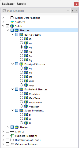
In the navigator, define the stresses to be displayed on the boundary surfaces of solids. The table lists the stresses of these surfaces according to the specifications set in the Result Table Manager .
The solid stresses are divided into the following categories:
- Basic Stresses
- Principal Stresses
- Equivalent Stresses
- Stress Invariants
Basic Stresses
Unlike surface stresses, solid stresses cannot be described by simple equations. The basic stresses σx, σy, and σz as well as the shear stresses τyz, τxz, and τxy are determined directly by the analysis core.
If a cube with the edge lengths dx, dy, and dz is cut from a 3D object with multiaxial loading, the stresses in each cubic surface can be split into normal and shear stresses. Neglecting the spatial force and also the stress differences on parallel surfaces, the stress state can be described by nine stress components in the cube's local coordinate system.
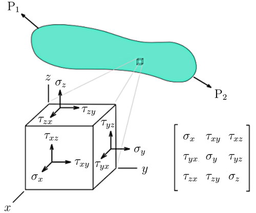
The matrix of the stress tensor is the following:
Principal Stresses
The principal stresses σ1, σ2, and σ3 result from the eigenvalues of the tensor as follows:
The maximum shear stress τmax is determined according to Mohr's circle:
Equivalent Stresses
The equivalent stresses σv according to von Mises can be determined by two equivalent formulas.
To determine the equivalent stress σv according to Tresca , the differences from the principal stresses are examined in order to determine the maximum value.
The equivalent stress σv according to Rankine is determined from the greatest absolute values of the principal stresses.
To determine the equivalent stress σv according to Bach , the principal stress differences are examined, taking into account Poisson's ratio ν, in order to determine the maximum value.
Stress Invariants
Stress invariants allow for a coordinate-independent and thus objective description of the stress state of a material. As scalar quantities, they remain unchanged under any rotation of the coordinate system and represent the physically relevant properties of these states independently of the selected tensor representation. Their particular significance lies in the fact that many mechanical phenomena—in particular plastic yielding, failure, and fracture—depend not on individual stress components but on invariant measures. Stress invariants thus form the basis of numerous established flow and failure criteria, such as the von Mises, Tresca, and Drucker-Prager theories.
The mean stress p is linked to the first stress invariant I1 and describes the hydrostatic stress. It is calculated from the arithmetic mean of the three principal stresses and represents the distance of the stress point from the coordinate origin on the space diagonal.
It characterizes the average axial stress state and is governing in terms of solid changes. Physically, p corresponds to a uniform pressure or tensile state that does not cause any change in shape, but only compression or dilatation. In many materials, especially in soil and rock mechanics as well as in pressure-sensitive materials, p significantly influences the strength and deformation behavior.
The deviatoric stress q is linked to the second invariant of the stress deviator J2. It is calculated as follows:
|
I1 |
First stress invariant |
|
I2 |
Second stress invariant |
|
J2 |
Second deviatoric stress invariant |
It describes the component of the stress state that is responsible for shape changes (shear distortions) without changing the solid. The deviatoric component drives plastic yielding and failure in ductile materials in particular. The von Mises yield criterion is based directly on J2 or q and illustrates that plastic deformation is primarily controlled by deviatoric stresses.
The Lode angle θ indicates the location of the stress point in the deviatoric plane. The deviatoric plane is divided into six sectors, so that −30° ≤ θ ≤ 30° applies. The angle is determined as follows:
|
J2 |
Second deviatoric stress invariant: 1/6 [(σ1 – σ2)2 + (σ2 – σ3)^2 + (σ3 – σ2)2] |
|
J3 |
Third deviatoric stress invariant: 1/27 (2σ1 – σ2 – σ3) (2σ2 – σ3 – σ1) (2σ3 – σ1 – σ2) |
A pure shear stress results for θ = 0, while for θ = 30°, the stress state σ1 > σ2 =& nbsp;σ3 occurs, which corresponds to a triaxial compression test. From θ = −30°, the stress state of a triaxial tensile test with σ1 < σ2 = σ3 results.
Strains
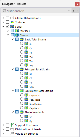
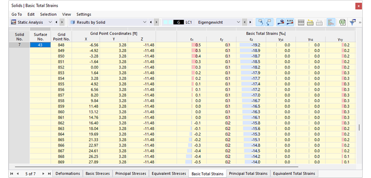
In the navigator, define the strains to be displayed on the boundary surfaces of solids. The table lists the stresses of these surfaces according to the specifications set in the Result Table Manager .
The solid strains are divided into the following categories:
- Basic Total Strains
- Principal Total Strains
- Equivalent total strains
- Strain Invariants
Basic Total Strains
The basic total strains including shear strains are determined directly by the computation kernel. The general definition of the tensor for the spatial strain state is as follows:
The elements of the tensor are defined as follows:
Principal Total Strains
The principal total strains ε1, ε2, and ε3 are determined from the basic strains.
Equivalent Total Strains
The equivalent total strains εv are determined according to four different stress hypotheses as follows.
|
γxy |
Engineering strain with 2ϵxy |
|
γyz |
Engineering strain with 2ϵyz |
|
γxz |
Engineering strain with 2ϵxz |
|
R |
see matrix |
|
R |
see matrix |
Strain Invariants
Strain invariants are properties of the strain tensor that remain independent of the orientation of the coordinate system. They allow for a clear distinction to be made between the change in solid and in shape of a material. This distinction is central to the analysis of material behavior, strength criteria, and plasticity models.
The volumetric strain invariant εv corresponds to the isotropic component of the total strains. It is determined from the principal strains:
The deviatoric strains εq or shear strains γs describe the pure change in shape without any change in solid. They are calculated as follows: