- 4.1 Nodes
- 4.2 Lines
- 4.3 Materials
- 4.4 Surfaces
- 4.5 Solids
- 4.6 Openings
- 4.7 Nodal Supports
- 4.8 Line Supports
- 4.9 Surface Supports
- 4.10 Line Hinges
- 4.11 Variable Thicknesses
- 4.12 Orthotropic Surfaces and Membranes
- 4.13 Cross-Sections
- 4.14 Member Hinges
- 4.15 Member Eccentricities
- 4.16 Member Divisions
- 4.17 Members
- 4.18 Ribs
- 4.19 Member Elastic Foundations
- 4.20 Member Nonlinearities
- 4.21 Sets of Members
- 4.22 Intersections
- 4.23 FE Mesh Refinements
- 4.24 Nodal Releases
- 4.25 Line Release Types
- 4.26 Line Releases
- 4.27 Surface Release Types
- 4.28 Surface Releases
- 4.29 Connection of Two Members
- 4.30 Joints
- 4.31 Nodal Constraints
- 6.1 Nodal Loads
- 6.2 Member Loads
- 6.3 Line Loads
- 6.4 Surface Loads
- 6.5 Solid Loads
- 6.6 Free Concentrated Loads
- 6.7 Free Line Loads
- 6.8 Free Rectangular Loads
- 6.9 Free Circular Loads
- 6.10 Free Polygon Loads
- 6.11 Free Variable Loads
- 6.12 Imposed Nodal Deformations
- 6.13 Imposed Line Displacements
- 6.14 Imperfections
- 6.15 Generated Loads
- 8.1 Nodes - Support Forces
- 8.2 Nodes - Deformations
- 8.3 Lines - Support Forces
- 8.4 Members - Local Deformations
- 8.5 Members - Global Deformations
- 8.6 Members - Internal Forces
- 8.7 Members - Contact Forces
- 8.8 Members - Strains
- 8.9 Members - Coefficients for Buckling
- 8.10 Member Slendernesses
- 8.11 Sets of Members - Internal Forces
- 8.12 Cross-Sections - Internal Forces
- 8.13 Surfaces - Local Deformations
- 8.14 Surfaces - Global Deformations
- 8.15 Surfaces - Basic Internal Forces
- 8.16 Surfaces - Principal Internal Forces
- 8.17 Surfaces - Design Internal Forces
- 8.18 Surfaces - Basic Stresses
- 8.19 Surfaces - Principal Stresses
- 8.20 Surfaces - Other Stresses
- 8.21 Surfaces - Contact Stresses
- 8.22 Surfaces - Equivalent Stresses - von Mises
- 8.23 Surfaces - Equivalent Stresses - Tresca
- 8.24 Surfaces - Equivalent Stresses - Rankine
- 8.25 Surfaces - Equivalent Stresses - Bach
- 8.26 Surfaces - Basic Strains
- 8.27 Surfaces - Principal Strains
- 8.28 Surfaces - Maximum Strains
- 8.29 Surfaces - Strains - von Mises
- 8.30 Surfaces - Strains - Tresca
- 8.31 Surfaces - Strains - Rankine
- 8.32 Surfaces - Strains - Bach
- 8.33 Solids - Deformations
- 8.34 Solids - Stresses
- 8.35 Solids - Strains
- 8.36 Solids - Gas Pressure
-
10.1 Printout Report
- 10.1.1 Creating or Opening Printout Reports
- 10.1.2 Working in the Printout Report
- 10.1.4 Adjusting Printout Report Headers
- 10.1.5 Inserting RFEM Graphics
- 10.1.6 Inserting Graphics and Texts
- 10.1.7 Printout Report Template
- 10.1.8 Adjusting Layouts
- 10.1.9 Creating Cover Sheets
- 10.1.10 Printing a Printout Report
- 10.1.11 Exporting a Printout Report
- 10.1.12 Language Settings
-
11.4 Editing Objects
- 11.4.1 Move and Copy
- 11.4.2 Rotate
- 11.4.3 Mirror
- 11.4.4 Project
- 11.4.5 Scale
- 11.4.6 Shear
- 11.4.7 Dividing Lines and Members
- 11.4.8 Connecting Lines and Members
- 11.4.9 Merging Lines and Members
- 11.4.10 Extending Lines and Members
- 11.4.11 Joining Members
- 11.4.12 Inserting Nodes
- 11.4.13 Inserting Members
- 11.4.14 Assigning Member Properties Graphically
- 11.4.15 Rounding Corners
- 11.4.16 Splitting Surfaces
- 11.4.17 Applying Tangents to Circles
- 11.4.18 Changing the Numbering
Most searched
Most visited
.png?mw=350&hash=c6c25b135ffd26af9cd48d77813d2ba5853f936c)


.JPG?mw=350&hash=d57486d45e0440dd9a6be9be91368a3e4f42f4b9)
.JPG?mw=350&hash=df48834f2d658081d5f412d698c4da41b73309b9)


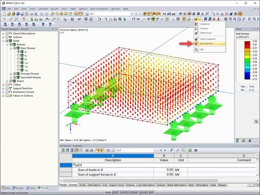
The results of solid stresses can be displayed as colored 3D points in the finite elements.
.png?mw=512&hash=ea9bf0ab53a4fb0da5c4ed81d32d53360ab2820c)
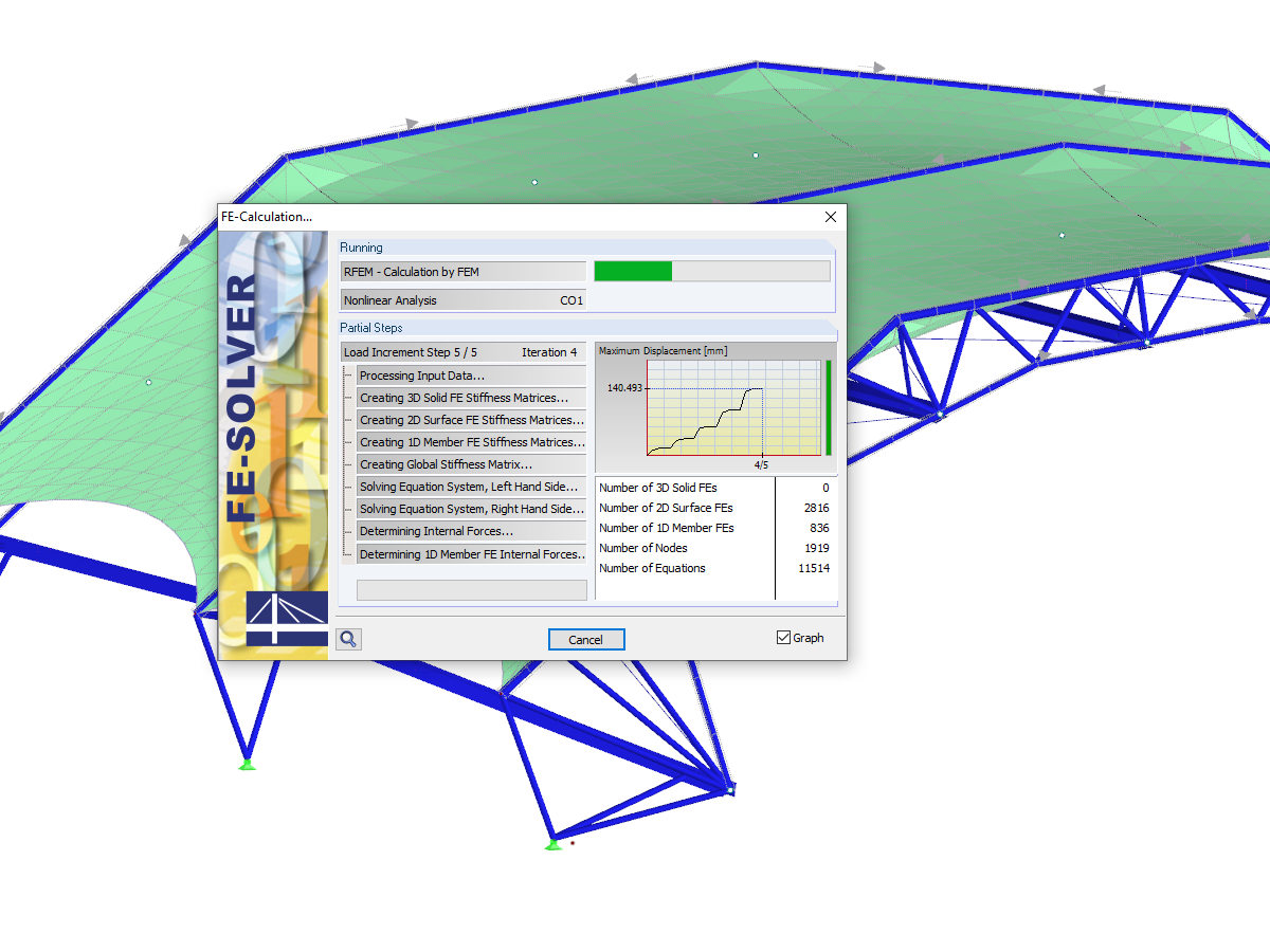
The number of degrees of freedom in a node is no longer a global calculation parameter in RFEM (6 degrees of freedom for each mesh node in 3D models, 7 degrees of freedom for the warping torsion analysis). Thus, each node is generally considered with a different number of degrees of freedom, which leads to a variable number of equations in the calculation.
This modification speeds up the calculation, especially for models where a significant reduction of the system could be achieved (for example, trusses and membrane structures).

Display extended strains of members, surfaces, and solids (for example, the important principal strains, equivalent total strains, and so on) in the Project Navigator - Results in RFEM as well as in Table 4.0.
For example, you can display governing plastic strains when performing the plastic design of connections with surface elements.

RFEM and RSTAB models can be saved as 3D glTF models (*.glb and *.glTF formats). View the models in 3D in detail with a 3D viewer from Google or Babylon. Take your VR glasses, such as Oculus, to "walk" through the structure.
You can integrate the 3D glTF models into your own websites using JavaScript according to these instructions (as on the Dlubal website Models to Download).
For example, can I define a member that absorbs all internal forces, except for the compressive axial forces?


.jpg?mw=350&hash=8f312d6c75a747d88bf9d0f5b1038595900b96c1)
