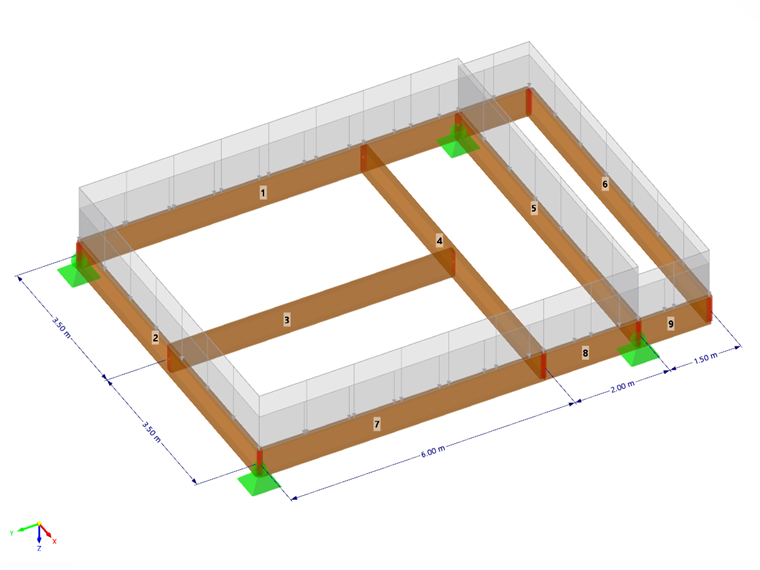
The Design Supports and Deflection tab is available in the editing dialog of a member or member set if the design properties of the object are activated (see image Activating design properties of a member). Design supports essentially have two functions:
- Definition of the boundary conditions for the 'Compression perpendicular to grain' design check
- Segmentation of the member or member set for the deflection design check of Timber Design
You can specify the default settings for the surface deflection analysis in the Deflection tab of the surface editing dialog.
Members
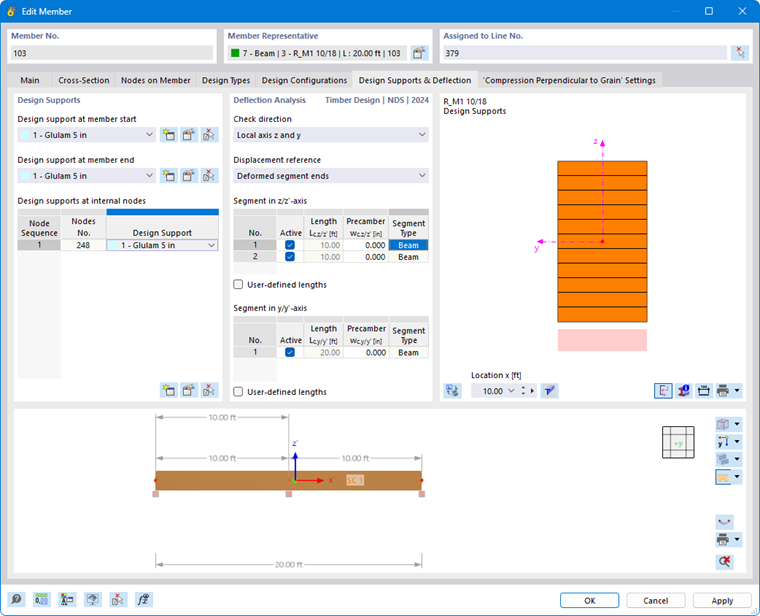
Design Supports
As mentioned, design supports are required for the 'Compression perpendicular to grain' design check at the support. You can specify specific parameters for this design check in the Compression perpendicular to grain tab. Design supports also offer the option to segment members and member sets for the deflection analysis.
You can assign design supports not only to the member start and member end, but also to internal nodes. In the table, nodes of the 'Node on Line/Member' type as well as standard nodes between members of a member set are therefore automatically preset.
Select a design support from the list or use the
 button to create a new type (see image New design support). You can use the
 button to modify the selected type, and the
 button to select an already assigned design support in the model.
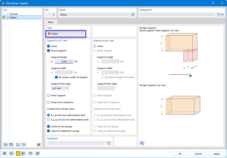
The dialog is adapted to the standard. If you have assigned a timber material to the member or member set, the Timber type is preset. Otherwise, select this option from the list.
You can use the two Active options to control for which directions (z-axis and/or y-axis) a design support exists. If the member is rotated by 90°, for example, you can deactivate the 'Support in z/z'-axis' and instead activate it for the y-axis.
If no 'Compression perpendicular to grain' design check is to be performed, but the design support is to serve for the segmentation of the member or member set for the deflection analysis, deactivate the Direct Support option: This way, no input is necessary for support geometry and position; the support serves only for segmentation for the deformation analysis. Alternatively, you could also select the 'General' design support type, for which the support pressure is not examined.
The support length is always related to the real beam. Starting from the structural system or the node, it is displayed in the dialog graphic, half in the positive x-direction of the member and half in the negative x-direction.
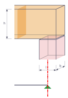
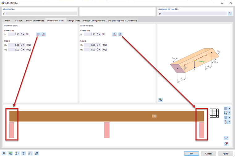
With the Support from Edge option, the program automatically detects whether a design support receives compression or tension forces. Accordingly, the 'Compression perpendicular to grain' design check is only performed in the case of compression forces.
If a design support acts at an intermediate support, select the Internal Support check box. Depending on the design standard, this specification is included in the determination of the effective support area.
With the Shear Force Reduction option, the shear force design check at the support is performed with the governing shear force. The shear force is considered in the design at a certain distance from the support edge. The distance depends on the design standard. This requires that the force acts on the opposite side of the support, i.e., usually on the top side of the beam.
If the compression stresses perpendicular to grain are too high, they can be absorbed by reinforcements using screws (only for EN 1995-1-1 and direct support). To do this, select the Reinforcement Elements check box. In the Reinforcement Elements tab, you can then define the properties of the fully threaded screws.
You can control with the Active for Fire Design check box whether the support pressure design check should also be performed for the fire case.
If a design support is not to be considered for the segmentation, deactivate the Active for Deflection Design option.
Deflection Analysis
Segments and Reference Lengths
In the right section of the Design Supports and Deflection tab, the segments resulting from the assignment of the design supports for the respective directions of the deflection analysis are listed. For each design check point in a segment, the displayed length Lc is used as the reference length for determining the limit value.
If you want to change the automatically determined reference lengths (for example, because the reference length of a curved member differs from the segment length), select the 'User-defined Lengths' check box. The values are then editable. These user-defined lengths are not automatically adjusted if you later change the member length in the model.
Limit Values for Beams and Cantilever Beams
The limit values of the deflection for beams supported on both sides and cantilever beams are managed in the Serviceability Configurations. The corresponding limit value is applied in the design check for each segment depending on the arrangement of the design supports: A segment with design supports on both sides or without design supports is assumed as segment type Beam, a segment with a design support on one side as Cantilever Beam.
Design Check Direction
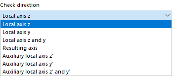
Use the 'Design Check Direction' to specify which deflection result values are to be checked. You can select the local axes y and z, the resulting deflection, and the local auxiliary axes y' and z' in the list. The segments below adjust accordingly.
Displacement Reference
With the options in the 'Displacement Reference' list, you can influence the deflection values to be checked for the design check:
- Undeformed System: The local deformation values uy and uz are taken directly from the results.
- Deformed Segment Ends: The deflection values are reduced for the design check by the deformation values of the start or end nodes, so that only the local deflections are checked.
Precamber
For the design check, you can consider a precamber for each segment and thus reduce the deflection value. The precamber is applied as a single-wave shape for beam segments, and as a linear curve for cantilever beam segments. Enter the precamber wc,z or wc,y as a positive value if it is opposite to the local member axis z or y. For the design check of the resulting direction, the components of the precamber are converted into the resulting direction.
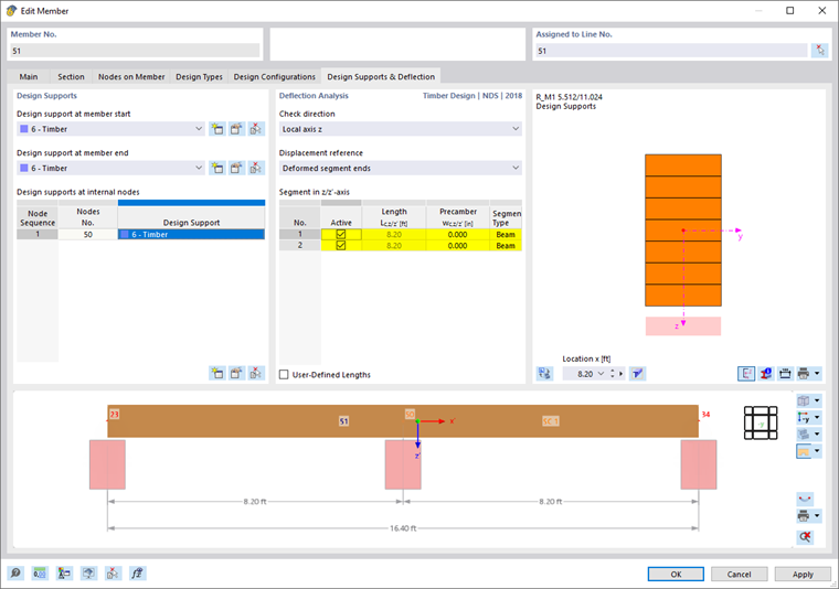
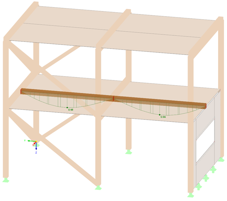
Example: In the following image, no design support was defined at the intermediate node No. 50. Consequently, the program recognizes only one segment and the reference length corresponds to the member length.
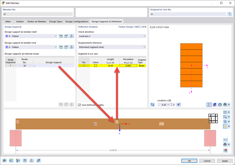
If a design support is defined at the intermediate node, two segments are recognized. The reference length adjusts accordingly.
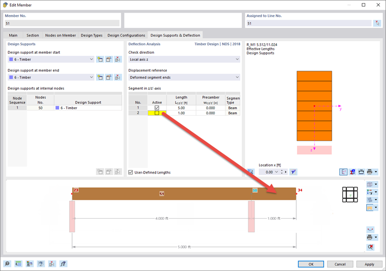
If a segment should not be checked for deformation, you can deactivate it using the check box:
Stiffening Elements
This tab is available for a design according to EN 1995-1-1 if you have selected the Stiffening Elements option in the 'Basic' tab. Here, you can define fully threaded screws that are considered as compression perpendicular to grain reinforcement elements in the "Compression Perpendicular to Grain" design check.
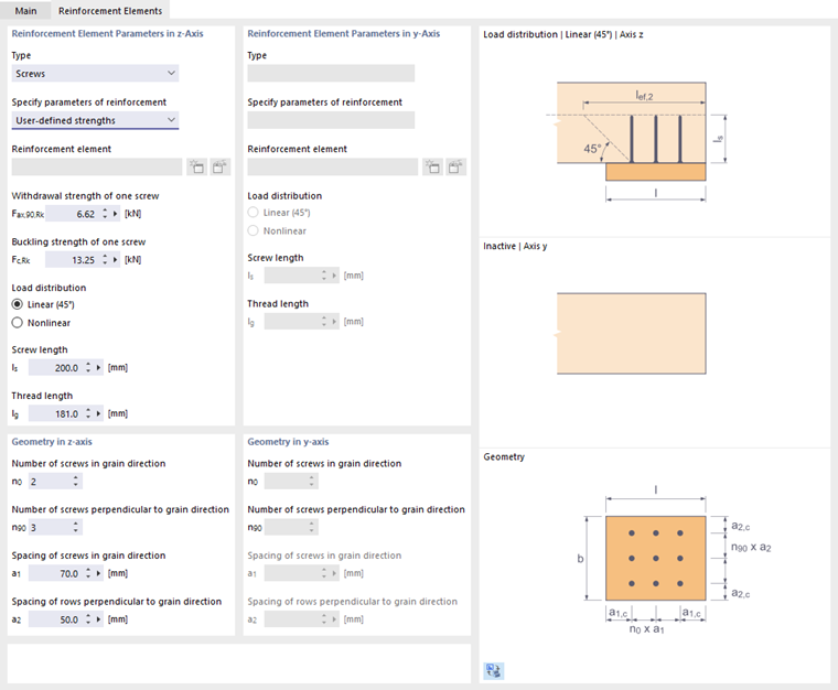
Currently, only reinforcement elements of the 'Screws' type are possible. Define the strengths and screw lengths according to the manufacturer's specification. You can also use the properties of stiffening elements that you have defined as Timber Screws. Use the corresponding option in the list for this.
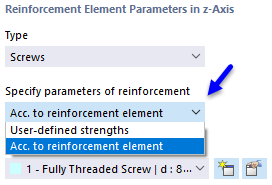
Select an already defined timber screw or create a new type using the
button.
In the 'Geometry in z-/y-axis' section, you define the number of screws and their arrangement.
The screws are checked for push-in and buckling. Additionally, the compression perpendicular to grain capacity in the plane of the screw tip is checked. The load distribution angle of the 'load distribution' can be considered linearly at 45° or nonlinearly – as described in [1] (also see the dialog graphic).
Surfaces
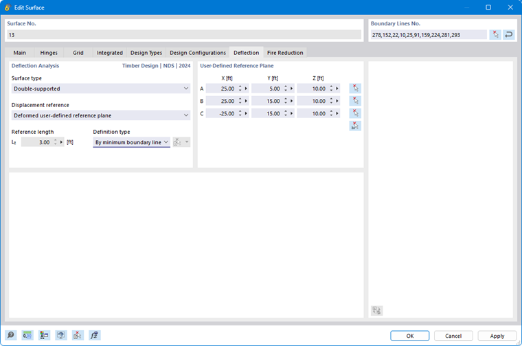
In the design of surfaces for the ultimate limit state, the stress components are examined. The design checks are based on the material properties and surface thicknesses. For the serviceability limit state design, however, surface-specific information is required. You can specify this information in the Deflection tab of the 'Edit Surface' dialog.
Surface Type
Use the surface type to specify which limit values of the deflection are applied in the design check. Two options are available in the list:
- Double-span
- Cantilever
The limit values are stored in the Serviceability configurations dialog for different design situations of surfaces with single- or two-sided support.
Displacement Reference
The displacement reference controls which reference model is used for the deformation analysis. The list contains three options:
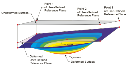
- Deformed User-defined Reference Plane: If the supports have very different displacements, you should specify an inclined reference plane for the displacement uz to be checked. Define the plane in the 'User-defined Reference Plane' section by three points of the undeformed system. RFEM determines the deformation of the three definition points, places the reference plane through these displaced points, and uses the related maximum deformation uz for the design check.
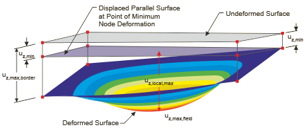
- Parallel Surface at the Location of the Minimally Deformed Node: This option is recommended for a yielding support of the surface. The maximum deformation uz is related to a reference plane shifted parallel to the undeformed system, which RFEM places through the node with the smallest displacement value uz,min.
- Undeformed System: The local deformations uz are taken directly from the results and used for the design check.
Reference Length and Definition Type
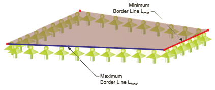
The limit value of the deflection depends on the reference length Lz. With the definition type options 'By Maximum Boundary Line' and 'By Minimum Boundary Line' (default), RFEM determines the length of the longest or shortest edge from the surface geometry and sets the reference length automatically. If you want to define the reference length, select the 'Manual' definition type in the list and then enter the value.
Elastic Support
The reference model is based on the assumption that the edges of the surface have a rigid support. If a surface or a surface set is elastically supported by a member element, the deformation analysis cannot be performed using the option of the displacement reference of the plane described above. In this case, the following procedure is recommended:
- Create a line along the relevant deformation.
- Assign a member of the Result Beam type to the line.
- Define a small integration width in the member properties, for example, 1 cm. This integrates the local surface deformations uz as member results.
- Assign a serviceability configuration for Members with the appropriate design parameters to the result beam. Deactivate the design for the ultimate limit state by selecting the -- option in the list when assigning the ultimate configuration.
The surface's deflection is thus checked in the form of a member design.
Compression Perpendicular to Grain
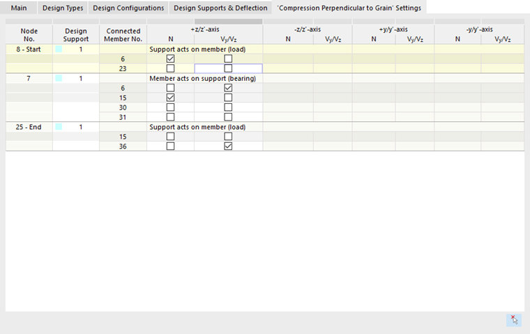
The Settings for 'Compression Perpendicular to Grain' tab is available in the editing dialog of a member or member set if a Direct Support exists at a design support. Here, you can describe the support situation of a spatial system for nodes of the member or member set that are implemented in the model without nodal supports – for example, members with an (indirect) support on another member.
The compression force required for the 'Compression perpendicular to grain' design check is determined from the internal forces of the members connected to the node. In the structural model, all members meet at one node, as shown in the following example.
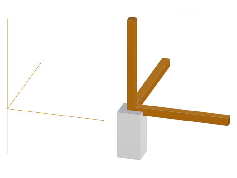
This simplification usually does not correspond to the actual conditions: Not every member directly transfers its axial or shear force into the support; instead, it presses on another member, which in turn transfers this force into the support with its internal forces. This results in a multitude of support situations.
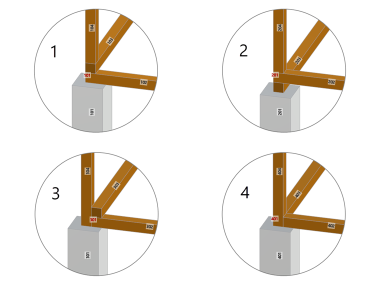
You can use the check boxes to control which members cause transverse compression forces and thus clearly define the support situation. This is described in a technical article using an example: