


The Members tab manages the detailed settings of the members connected to the node being designed.
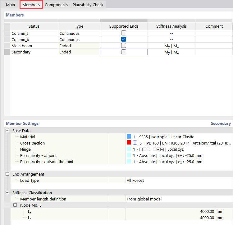
Members
The table lists the members connected at the node. As described in the Basis chapter, these are groupings ("types") of members with identical properties. The designations used in the 'Basis' tab can be found in the Status column. You can rename them here if necessary.
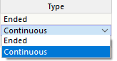
In the Type column, you can specify whether a 'Member end' is present at the node to be designed or whether the member is 'Continuous' there.
In the Supported Ends column, you define which member in the Equivalent FE Model of Steel Joint is to receive a support at the member end located away from the design node. You can activate supports for several members, but at least one member must remain unsupported for load application: The loading is applied to members that are not supported. Detailed settings for the support and load application at the respective member ends can be made in the Settings Member Settings.
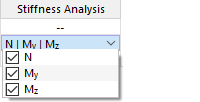
The Stiffness Analysis column appears if you have specified a stiffness analysis configuration for the Additional Analysis in the 'Basis' tab. You can specify here for which member the stiffness is to be determined taking the connection components into account. In the list, select the internal forces relevant for the stiffness analysis.
Optionally, you can enter a Comment for the respective status in the last column. It is synchronized with the 'Basis' tab.
Member Settings
In the Base Data category, the used settings of the selected member, such as material and cross-section, are displayed. If hinges or eccentricities exist on the selected member, these are also indicated.

If you click into the cell of the described property, you can edit it via the
 button.
The End Arrangement category manages detailed information on the boundary conditions of the equivalent model. For supported ends, the Support Type is defined as either fixed or pinned. With a fixed support, all degrees of freedom are restrained (default); with a pinned support, only the displacements and axial rotation are restrained. For free member ends, the Load Type is specified accordingly. By default, all internal forces from the main model are also applied in the equivalent model ('All Forces'). However, you can also have only specific internal force components applied.
The Stiffness Classification category is only available if you have assigned internal forces to a member for the stiffness analysis (see image Internal Forces for Stiffness Analysis).
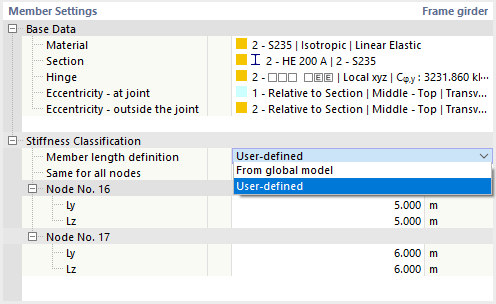
The 'Definition of the Member Length' affects the classification of the connection. The member length is taken from the model geometry and preset as the effective length in the direction of the member’s y- and z-axis, respectively. If these values for Ly and Lz do not correspond to the circumstances, select the 'User-defined' option from the list. You can then assign the lengths to the design nodes individually. This is necessary, for example, if a member is divided between the columns: In this case, specify the span between the columns. If the parameters are identical for the nodes managed in the connection, activate the 'Same for all nodes' check box and specify the lengths across all nodes.
Graphics Window
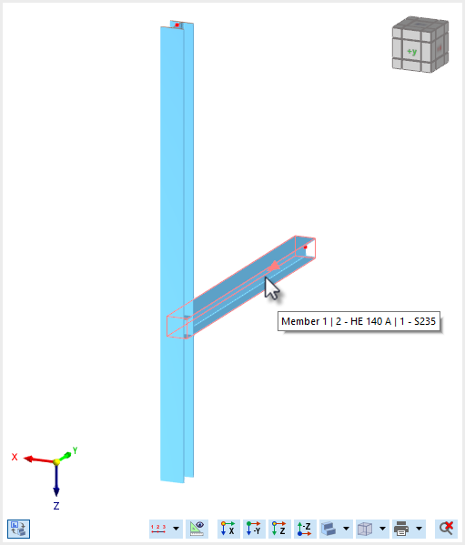
In the graphic, only one connection node is displayed now, which represents all design nodes via the grouping. When you move the mouse over a member, information about the status, cross-section, and material is displayed.
Use the
 button below the graphic on the left to switch between the symbolic representation of the connection and the actual view.