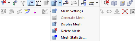
The "Mesh Settings" dialog box manages general specifications for the generation of the FE mesh. You can open this dialog box by selecting Mesh Settings in the Calculate menu, or by using the
 button.
General
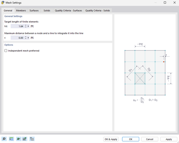
In the General tab, you can adjust the default mesh size used by RFEM when generating the FE mesh.
General Settings
The "Target length of finite elements" controls the mesh size with which the FE mesh is generated. The shorter the FE length, the tighter the mesh and (generally) the more accurate the results. However, this also increases the amount of data and the computing time, as additional equations have to be solved for each additional FE node. A tighter mesh also means that singularity effects become more pronounced.
Under special conditions (for example, the same number of nodes at close intervals on opposite edges of surfaces), the meshing algorithm may ignore the desired length and generate a regular mesh instead.
The "Maximum distance between a node and a line" indicates the distance of a node from a line at which it is automatically integrated into the line. If the distance of the node is greater than this limit value, RFEM creates a new FE node.
Options
The "Independent mesh preferred" check box allows you to create specific FE meshes for surfaces or solids with integrated objects. In the case of a slab on a soil massif, for example, the solid of the soil massif can be modeled with a larger FE mesh than the slab. The number of finite elements is significantly reduced in this way.
Members
The Members tab controls how the FE mesh is created on members.
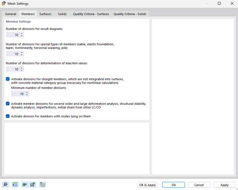
If necessary, you can adjust the "Number of divisions" for result diagrams, special member types, and for the determination of extreme values. If you increase the divisions, you can achieve a refined result diagram. In most cases, however, the default settings are sufficient.
The value of "Divisions for result diagrams" affects the graphical result diagram of the members that do not have any further FE mesh divisions, for example, due to FE mesh refinement or connected surfaces. With a division of 10, the length of the longest member in the structural system is divided by 10. This structural system-related division length is then used to determine the graphical result diagrams at the intermediate points for each member.
The "divisions for straight members with concrete material category" influence the nonlinear reinforced concrete calculation of members in the cracked state. Among other things, the Concrete Design add-on can determine the stiffness (uncracked/cracked) in each finite element for the deformation analysis.
The "Activate member divisions for large deformation analysis, structural stability, dynamic analysis" option allows you to also divide beam members using intermediate nodes for calculations according to the large deformation analysis or regarding stability and dynamics, and thus determine them with greater accuracy. The number of divisions for "special types of members" is applied here (the second text box above).
With the "Activate division for members with nodes lying on them" option, RFEM generates FE nodes at member locations where other members are connected to the member, but have no connection to it.
Surfaces
The Surfaces tab controls how the FE mesh is created on surfaces.
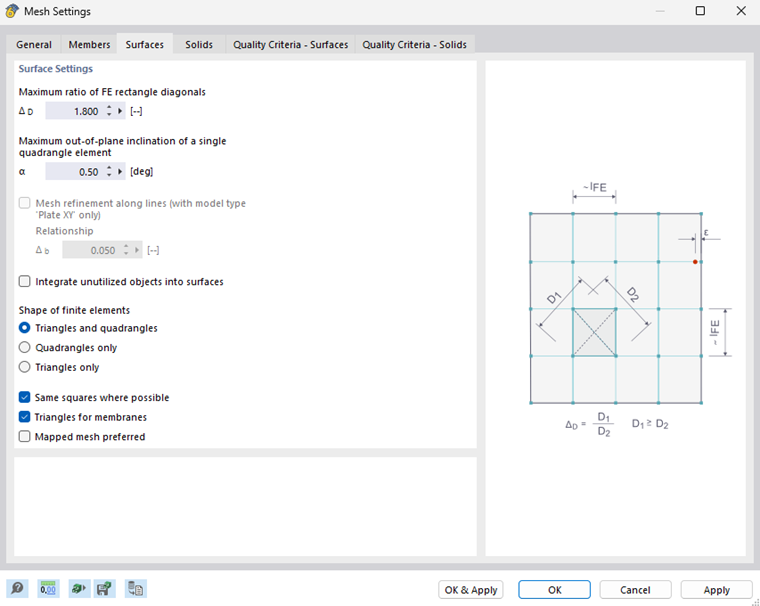
The most accurate results are obtained for finite elements that are as close as possible to the shape of a square. For a square, the ratio of diagonals is D1/D2 = 1. In the "Maximum ratio of FE rectangle diagonals" text box, enter the limit value ΔD for the diagonal ratio. If you reduce the value, more triangular elements will be created. On the other hand, a value that is too large leads to the generation of elements with very acute or reflex angles. This may result in numerical problems.
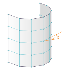
A curved surface is covered by plane elements in the FE mesh. The inclination angle α defines the "Maximum out-of-plane inclination of a single quadrangle element". This value describes the angle between the normals of two elements (see the image Inclination Angle α). If the allowable inclination angle is exceeded, they are subdivided into triangular elements.
The “Mesh refinement along lines” feature for surface models of the “2D | XY | Plate” type is still in development.
Using the "Integrate unutilized objects into surfaces" option you can also create FE nodes on objects that have no other function for a surface (for example, free nodes without support or loading, constructional lines in surfaces). This function is deactivated by default so that structurally irrelevant objects do not distort the FE mesh.
You can modify the "Shape of finite elements" using three options:
- Triangles and quadrangles: Default setting
- Triangles only: Option if quadrangles cause strong mesh distortions
- Quadrangles only: Option for increased accuracy of results
For additional control options, use the "Same square bars where possible" and "Triangles for membranes" check boxes.
With the "Mapped mesh preferred" option, RFEM tries to adapt the FEM mesh to the boundary lines of the surfaces. You can define this type of FE mesh generation separately for each surface ("Mesh Refinement" tab in the "Edit Surface" dialog box).
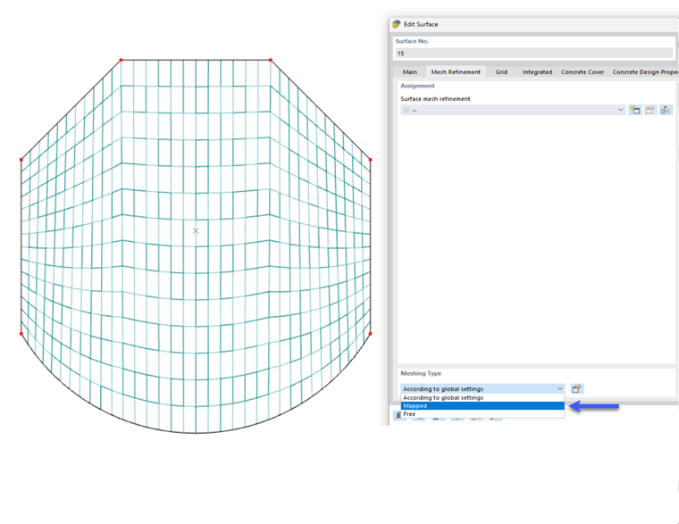
A mapped mesh is composed exclusively of quadrangles. In general, a mapped mesh provides "more accurate" results. Since there are also fewer unknown variables in the equation system, this method is recommended for mesh generation.
Solids
The Solids tab controls how the FE mesh is created on solids.
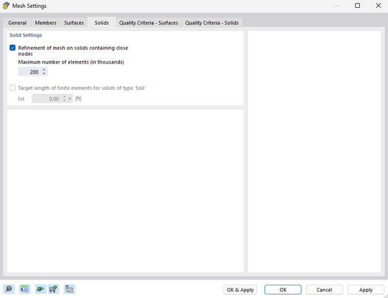
If you activate the "Refinement of mesh on solids containing close nodes", RFEM performs a mesh refinement for solids whose nodes are very close to each other. In this way, the nodes are correctly determined with the FE mesh. The mesh size of the solid arises from the shortest distance of the nodes.
The "Maximum number of elements" represents the upper limit of the 3D elements created.
You can access the "Target length of finite elements for solids of type Soil" check box if the Geotechnical Analysis add-on is activated (a license is required). This allows you to define a specific default mesh size LFE for soil massifs and create larger solid meshes without "mesh refinements".
Quality Criteria – Surfaces
The Quality Criteria – Surfaces tab manages the quality specifications for the generation of 2D elements.
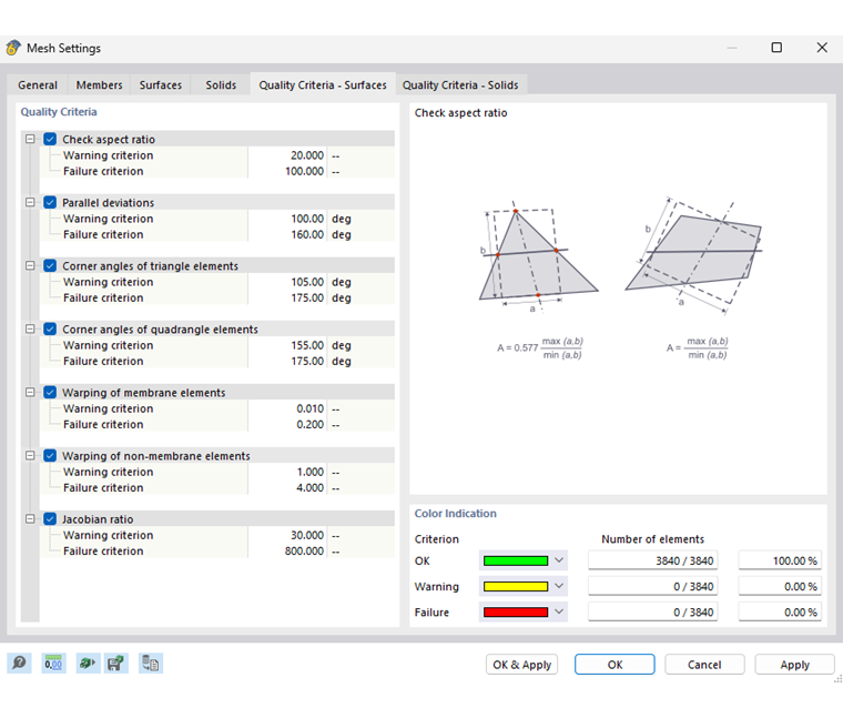
Quality Criteria
This dialog section specifies various criteria that are checked after the FE mesh has been generated. If you deactivate a criterion, RFEM does not perform the corresponding check.
For each type of check, you can specify the value at which a "Warning criterion" and a "Failure criterion" apply.
Color Indication
After generating the FE mesh, RFEM shows the "Number of elements" that meet the quality criteria as well as those for which there is a problem. This allows you to evaluate the consistency of the FE mesh.
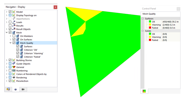
The quality of the FE mesh can also be checked on the model: In the "Navigator – Display", activate the Mesh Quality in the "Mesh" category.
Quality Criteria – Solids
The Quality Criteria – Solids tab manages the quality specifications for the generation of 3D elements.
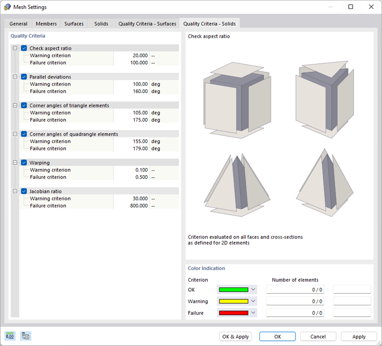
Quality Criteria
This section specifies various criteria that are checked after the FE mesh has been generated. If you deactivate a criterion, RFEM does not perform the corresponding check.
For each type of check, you can specify the value at which a "Warning criterion" and a "Failure criterion" apply.
Color Indication
After generating the FE mesh, RFEM shows the "Number of elements" that meet the quality criteria as well as those for which there is a problem. This allows you to evaluate the consistency of the FE mesh.
Wind Simulation
The ‘’‘Wind simulation’‘’ tab is displayed if you have activated the ‘’Wind Simulation’’ add-on for the CFD simulation RWIND in the model base data.
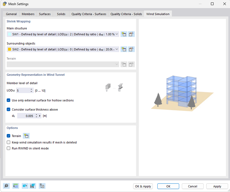
The parameters are described in the chapter Mesh Settings – Wind Simulation of the RWIND manual.