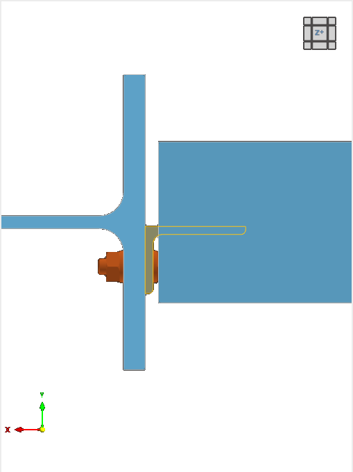
The Cleat component connects a member plate to a reference member. The most common usage of a cleat connection is for pinned connections. It is also possible to connect a second member within this component.
To Connect
The first category of the component settings manages the definition of the connected member(s) and reference member.
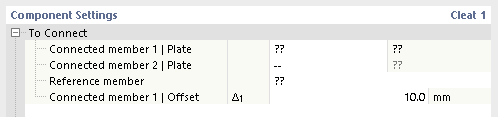
In the "Connected Member 1 | Plate" row, define the connected member and its member plate. The second connected member is optional.
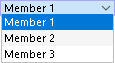
Specify the part of the member to which the cleat is connected.

Next, select the reference member. Its member plate is detected automatically.
In the "Offset" row(s), you can define the distance between the connected member face and the reference member.
Cleat
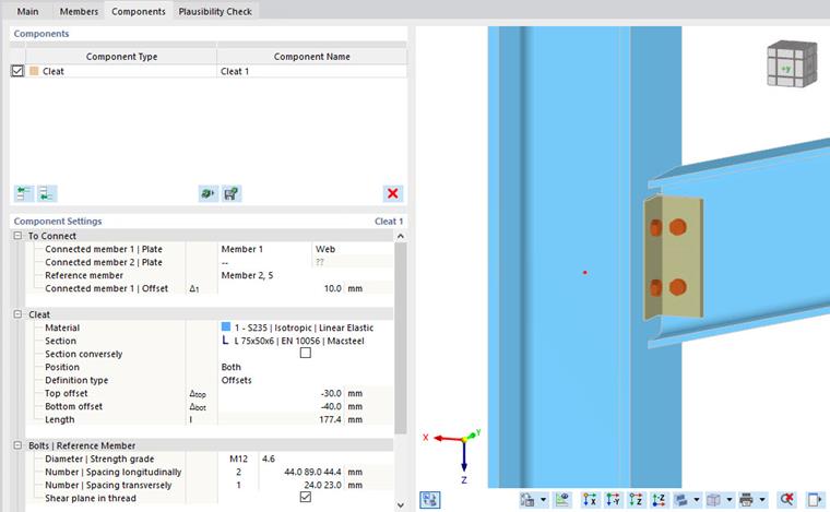
The subsequent category controls the definition of the cleat, starting with the material and section. If you have set two connected members, you can define the parameters of each cleat separately.
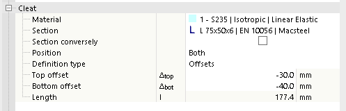
When the "Section conversely" check box is cleared, the cleat is placed with its section strong axis perpendicular to the reference beam. When that option is selected, the strong axis is parallel to the reference beam.

The "Position" refers to the placement of cleats with respect to the connected member plate: "Front", "Rear", or "Both" sides of the plate.
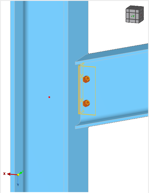

You can define the size of the cleat either by "Offsets" or by "Length and position". Select the relevant option from the list.


When you define the cleat by "Offsets", its size is derived from the top and bottom distances from the member edges that you can set. You can check the length of the cleat in the final row, but you cannot change it.
When you select the "Length and position" option, you can enter the size of the cleat directly. You can change the position by defining an eccentricity that is measured from the center of the connected member to the center of the cleat.
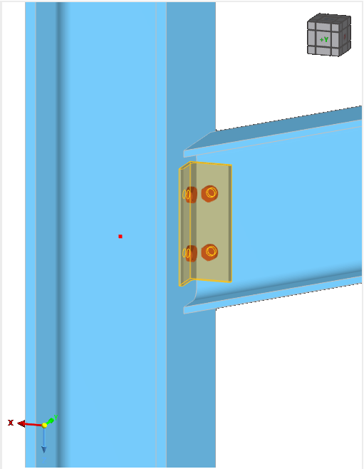
Bolts
Each cleat has two bolt groups – one for the reference member and one for the connected member. The last categories manage the properties of the bolts.
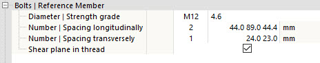
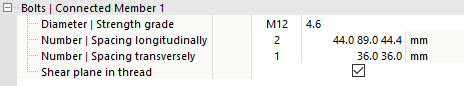
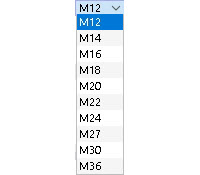
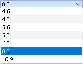
Define the bolt diameter and bolt class in the first row by selecting the adequate entries from the lists.
In the next two rows, you can define the spacing of the bolts with respect to the horizontal and vertical directions.
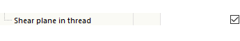
When the "Shear plane in thread" option is activated, the lower strength (reduced area) according to the selected design standard is considered for the bolt shear check.