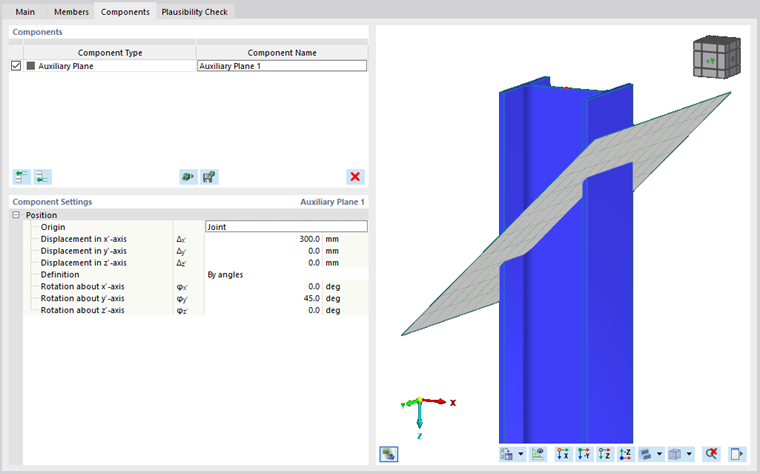
There are many components to modify members or other structural components in the joint. One of these is Auxiliary plane. It can be used to represent a surrounding structure that is not modeled using the current model, or as a virtual plane that can be used for further modifications and for positioning other components.
Position
The sole input node is used for positioning the auxiliary plane in the joint.
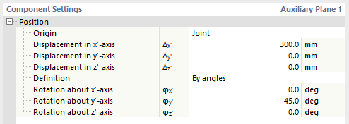
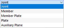
First, you have to select the origin component to which the displacements will be related. The default value is Joint (the point of origin of the whole joint), but you can also choose Member, Member Plate, Plate or another Auxiliary Plane as the reference component. Based on the coordinate system of the reference component, you can move the auxiliary plane to fit your needs.
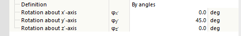
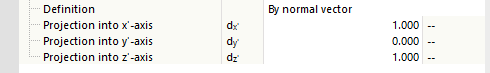
To define the rotation of the auxiliary plane, you have two possibilities: By angles or By normal vector. For the By angles definition, you can specify the rotation about the main local axes of the auxiliary plane. When using the By normal vector definition, you define the three components of the normal vector as projections into the main local axes of the auxiliary plane.