


Dimensions make an important contribution to the understanding of modeling. You can enter different types of dimensions that you can apply as user-defined.
You can use the functions of the
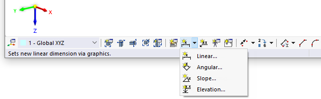
![]() button in the CAD toolbar to set dimensions directly on the model.
button in the CAD toolbar to set dimensions directly on the model.
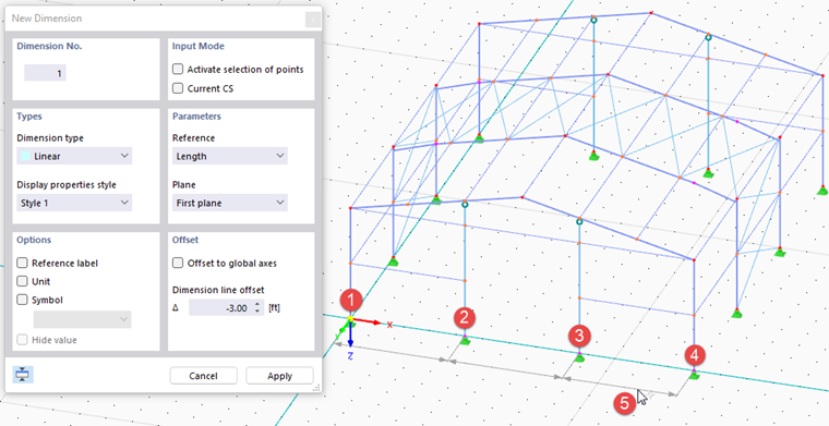
Define the parameters in the small New Dimension dialog box. Then, click the dimension-defining objects in the work window.
Main
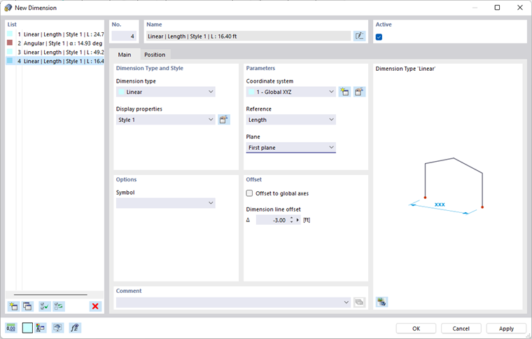
In the Main tab, define the type of dimension and how it is to be represented.
Dimension Type and Style
Various "Dimension types" are available for selection in the list. They correspond to the functions of the buttons (see the image Buttons for Dimensions).
| Linear | Length(s) between two or several nodes |
| Angular | Angle between three nodes or two members |
| Slope | Inclination angle between a line and a plane |
| Elevation | Elevation number of a node |
The "Display properties" control the dimension symbols and fonts used to display the dimension. You can check the current "Style" using the
![]() button: The "Display Properties" dialog box appears with a preview of the dimension. There, you can adjust the style for the individual dimension types, if necessary.
button: The "Display Properties" dialog box appears with a preview of the dimension. There, you can adjust the style for the individual dimension types, if necessary.
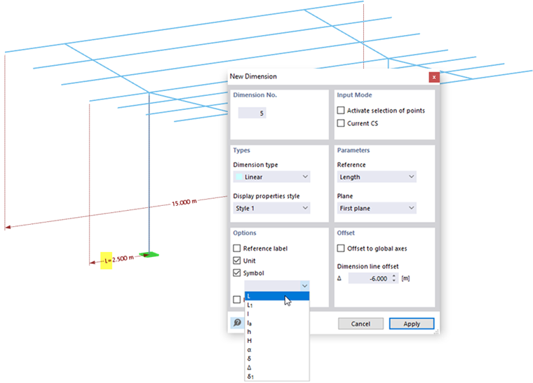
Options
You can supplement the dimensioning with a dimension symbol. Enter the "Symbol" or select the relevant entry from the list.
Parameters
In this dialog box section, you can define the reference parameters for dimensions of lengths.
Define the "Coordinate system" to which the dimension refers. You can select a user-defined coordinate system in the list or create a new one using the
![]() button.
button.
By specifying the "Reference", you can control whether the dimensioning refers to either the true length between definition points, or the projection into one of the global directions.
The 'Plane' determines where the dimension line is applied. This setting refers to the axes of the coordinate system. When switching between the "First plane" and "Second plane" list entries, you can see the effect in the dialog graphic or work window.
Offset
The "Dimension line offset" Δ describes the distance of the dimension line from the reference objects. In the button dialog box, you can define this distance graphically (see Step (5) in the image Setting Dimension Graphically).
If you activate the "Offset to global axes" check box, you can define the distance of the dimension line with the global coordinate reference.
Position
The Position tab manages the dimension-determining objects and parameters.
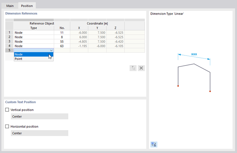
Dimension References
The input options in this dialog section depend on the dimension type. For length dimensions, the reference objects are managed in a table: In the "Type" column, define the type of the reference object. Then, enter the "No." of the node or point. When the text box is activated, you can also define the reference object graphically using the
![]() button. The table thus offers the option of relating the dimension line to other nodes without having to delete and redefine the dimensioning.
button. The table thus offers the option of relating the dimension line to other nodes without having to delete and redefine the dimensioning.
For an angular dimension ("Slope" type), you can define in this dialog tab the governing "Member", the "Direction" of the angle, and the "Position" of the dimension in relation to the member start or member end.
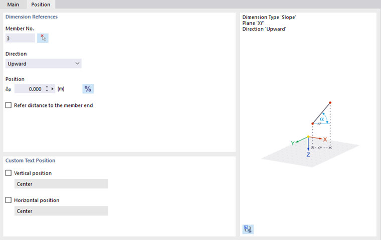
Custom Text Position
The dimension text is centrally arranged by default. To adjust the "Vertical position" or the "Horizontal position", select the corresponding check box. You can then select the appropriate position in the list.
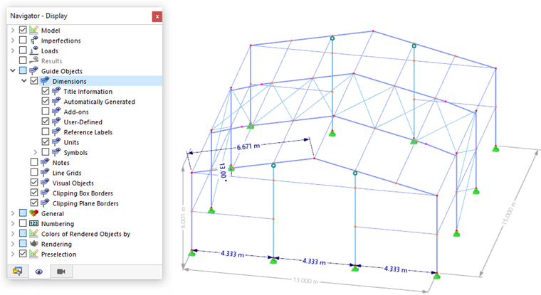
Display of Dimensions
You can show or hide the display of dimensions in the "Navigator – Display". In the Dimensions category, there are more options available to set the display. For example, you can activate the display of units or Symbols.
In the "Navigator – Data", you can control the display of dimensions individually.
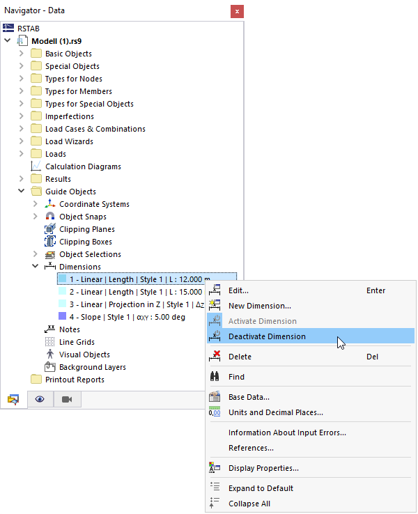
As an alternative, you can use the check box in the Active dialog box section (see the image New Dimension).
Dimensions for Member Results
Dimensions can also be used for display and evaluating member results. To do this, activate the Results on Members check box in the lower section of the Navigator – Results in the Dimension category.

If member results are displayed in the work window, the deformation or extreme values are also specified for the defined dimensions. The values are adjusted to the result type you have selected in the upper section of the navigator.