The load wizard facilitates the task of placing wind loads on members of the model in compliance with standards.

Main
The Main tab manages the geometry parameters of the roof and, if applicable, the building.
Structure Definition
Specify whether wind loads should be generated on the roof and walls of a building or only on the roof. The list contains the following options:
- Buildings
- Canopy roofs
Type
Depending on the structure definition, the following building and roof shapes are available to select from in the list:
- Vertical walls with flat/monopitch roof
- Vertical walls with duopitch roof
- Flat/Monopitch roof
- Duopitch roof
When creating wind loads on walls carrying a roof, define the "Base corner nodes" of the building first. Use the
![]() button and click the four corner nodes of the floor area one after the other in the work window.
button and click the four corner nodes of the floor area one after the other in the work window.
Then you define the boundary of the roof plane (as with wind loads only on roofs) by again clicking the four or six corner nodes of the plane(s) using the
![]() button. In the case of roof overhangs, specify the upper wall nodes, not the roof nodes.
button. In the case of roof overhangs, specify the upper wall nodes, not the roof nodes.
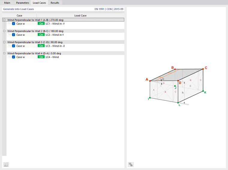
Set Wind Perpendicular to / in Direction
The table lists four wind flow directions. They refer to the roof sides in accordance with the graphic scheme. You can use the check boxes to control which directions are to be considered for the load generation.
Set Loaded Wall / Roof
The table provides an overview of the properties of the wall or roof plane(s). If necessary, you can use the check boxes to exclude any wall or roof side from the load assignment.
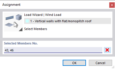
Generated on Members Nos.
This dialog section shows the members that get a proportional wind load. The entries are available as soon as the wind load is generated from the complete data after using the
![]() button.
button.
To exclude certain members from the load transfer, click into a field of the "Without Load" column. With the
![]() button, you can then select the members in the work window that are load-free, such as bracings or purlins. You can also specify a template member that runs parallel to the unloaded members. In this way, you do not need to select the members individually.
button, you can then select the members in the work window that are load-free, such as bracings or purlins. You can also specify a template member that runs parallel to the unloaded members. In this way, you do not need to select the members individually.
Options
The “Partial Areas” check box allows you to generate loads for specific zones of the building envelope. The wind load is only applied to the elements of the areas that you can specify in the Partial Areas tab.
Partial Areas
In the Partial Areas tab, you can define zones of the roof and wall areas where the wind load acts. The loads are only generated for the elements of these partial areas. The remaining areas do not receive any wind loads.
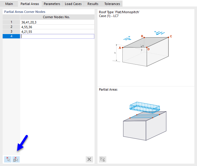
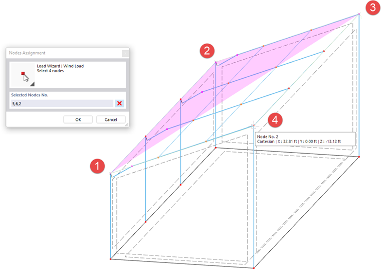
Define the partial areas line by line by entering their ‘‘corner nodes’’ You can also define the partial areas graphically using the two buttons at the end of the table.
|
|
Click on the corner nodes of a partial area in sequence (see the image Defining Nodes). |
|
|
Click on the cells one after the other (see the image 6/000262#image023916 Selecting Cells). |
Parameters
In the Parameters tab, you can define the load parameters and consider special boundary conditions for the generation.
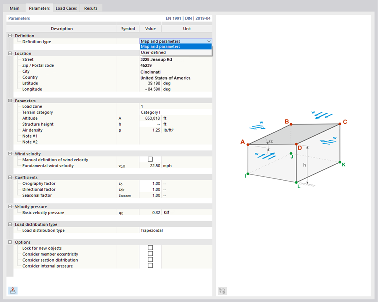
Definition
If you have adopted the location from the online map in the Model Parameters tab for the base data, the "Map and parameters" definition type is preset. The wind load is determined automatically. Use the
![]() button to open the wind load map in this tab also.
button to open the wind load map in this tab also.
The "User-defined" definition type allows you to manually define the wind zone, terrain category, altitude, and value of the basic wind velocity.
Parameters
If the "Load zone" (for the German National Annex) is not entered automatically, you can select it in the list. The entries are aligned with the standard you defined in the Standards I tab for the model base data.
The "Terrain category" and the "Altitude" (for DIN) are usually preset from the model parameters, but can also be defined manually. They affect the basic value of the basic wind velocity. The "Structure height" is taken from the model geometry for load wizards used for walls. In the case of wind loads acting on roofs, the value must be defined manually.
Wind Velocity
The basic value of the fundamental wind velocity vb,0 is preset from the geographical information. If you want to change the value, select the "Manual wind velocity definition" check box (for DIN).
Coefficients
The "Directional factor" cdir and the "Seasonal factor" cseason are included in the determination of the basic wind velocity (see EN 1991-1-4, 4.2).
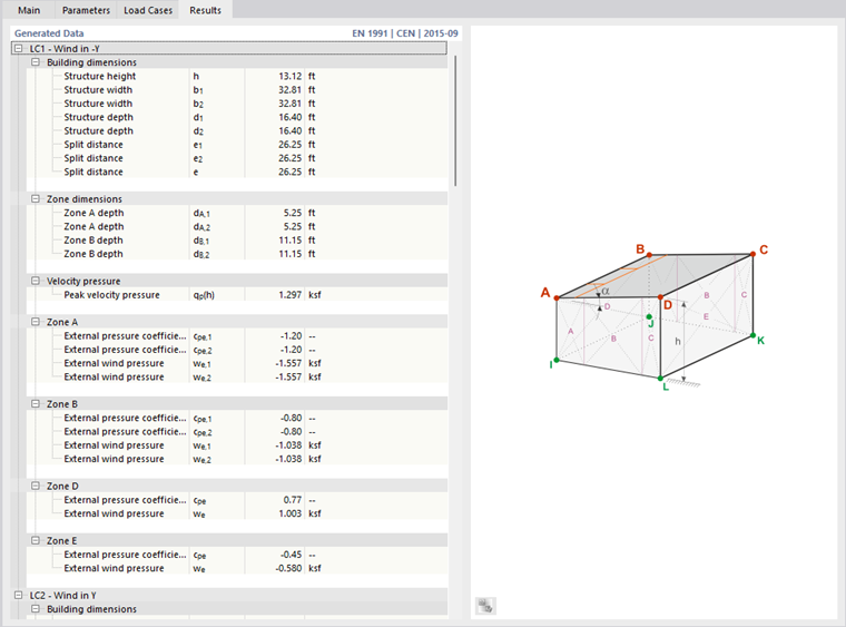
Velocity Pressure
The "Basic velocity pressure" qbEN 1991-1-4, (4.10) is required to determine the peak velocity pressure, which includes the mean and short-term velocity changes. === Load Distribution === Currently, only trapezoidal loads resulting from the load components are generated on members. === Options === If you select the "Lock for new objects" check box, the wind load acts only on the currently available members of the planes according to the definition set in the "Main" tab. Any members you add in a wall or roof plane later will not get any components of the wind load. The "Consider member eccentricity" option controls whether the wind load acts on the members in the plane without considering eccentricities (default setting). If you activate the check box, the load is not applied to members for which an out-of-plane offset is available. With the "Consider section distribution" check box, you can control whether the wind load resulting from a taper definition also acts on the inclined members (default setting). If you activate the check box, the wind load will not be applied to members in the load plane that have a non-uniform cross-section distribution (see the Section chapter). If you select the "Consider internal pressure" check box, you can define the internal pressure coefficients cpi for each of the wind directions in an additional category. This allows you to determine effects produced by openings placed in walls. The technical article about the [[#/en/support-and-learning/support/knowledge-base/001453 Determination of Internal Pressure Coefficient cpi for Single-Story Buildings According to EN 1991-1-4]] provides detailed information on this topic. When generating loads according to AISC 7, you can also consider the “torsional moment” that generates wind load around the building axis. This additional moment always acts centrally around the building axis. The wizard generates various load cases for positive or negative torsion. == Load Cases == The '''Load Cases''' tab controls the load cases where the wind loads are stored.
For the individual wind directions, define the load cases in which the wind loads are to be stored. As described, for example, in EN 1991-1-4, Table 7.3a, different pressure coefficients have to be taken into account for a monopitch roof. For this purpose, pressure loads are created in "Case w+", suction in "Case w-". You can create the corresponding load cases with the