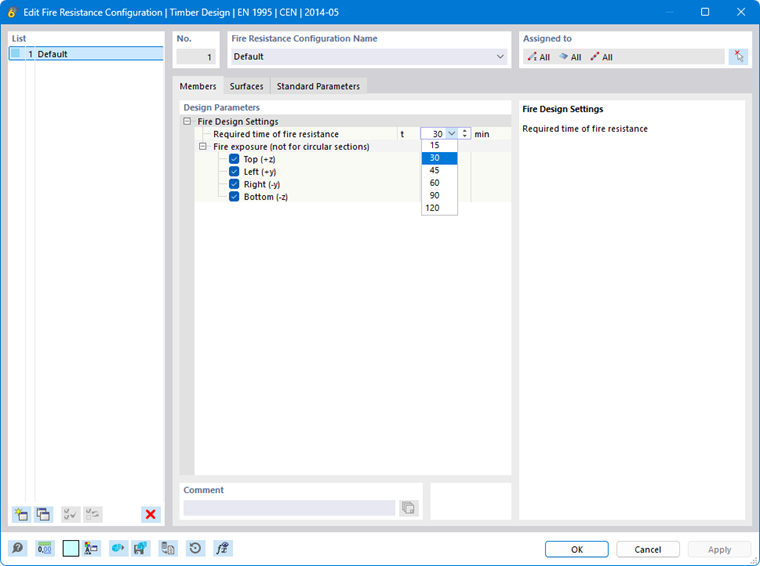
In the Fire Resistance Configuration dialog box, you can define basic settings for the fire resistance design of members and surfaces (“Fire Resistance Design”). Here, you specify how long the objects have to withstand the effects of fire and which sides of the cross-section or surface are exposed to the fire.
The concept of design configurations is described in the chapter Timber Design. The fire resistance configurations are also aligned with the standard that you specified in the model base data for the timber design.
Members
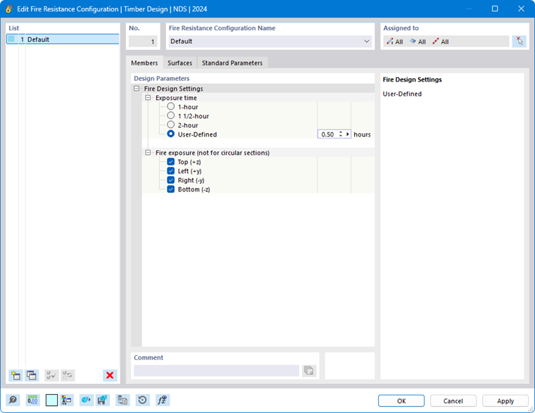
In the Members tab, you can configure the fire design settings for members and member sets.
The design is currently subject to a limitation that restricts it to simple rectangular cross-sections
 and circular cross-sections
 . For all other cross-section types, an error message will appear.
Required Duration of Fire Resistance / Exposure Time
Specify how long the members are required to resist fire or how long the fire exposure lasts. Some standards provide options for typical requirements. However, you can also specify a user-defined fire exposure time.
Fire Exposure
Use the check boxes to control which sides of the cross-section are exposed to fire.
For a circular cross-section
, defining fire exposure is not relevant because the cross-section is reduced along its entire circumference.
The charring resulting from the fire exposure and fire duration of the cross-section leads to a residual cross-section, which is used for design according to the respective standard.
Surfaces
In the Surfaces tab, you can configure the fire design settings for surfaces.
Fire Design Settings
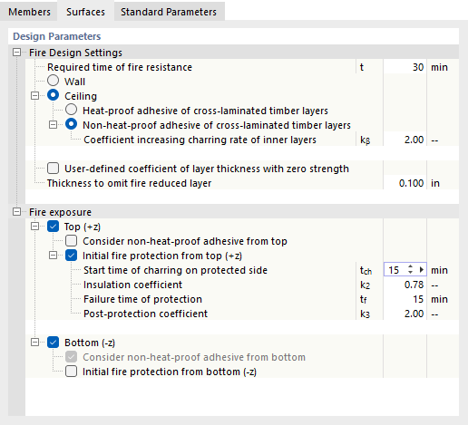
Specify how long the surfaces are required to resist fire or how long the fire exposure lasts. For design according to '''EN 1995-1-2''' [1], you can specify whether the fire is occurring in a wall or a ceiling and whether the cross-laminated timber layers are bonded with a heat-proof adhesive. In the case of heat-proof adhesive, the charring distribution progresses linearly. If the adhesive is non-heat-proof, an incremental charring distribution is assumed.
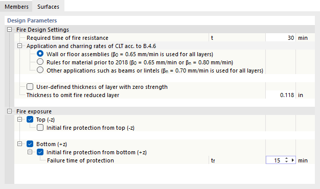
In the design of cross-laminated timber (CLT) structural components according to ‘’'CSA O86'‘’ [2] B.4.6, specific charring rates may be applied in the following cases:
- Flat structural components ,such as walls or floor slabs
- Structural components made of a material manufactured according to earlier editions of ANSI/APA PRG 320 (prior to 2018)
- Other structural components, such as beams or lintels
The “User-defined layer thickness with zero strength” option provides the option to reduce the cross-section by a layer with zero strength to account for the reduction in strength of the heated timber beyond the charred area.
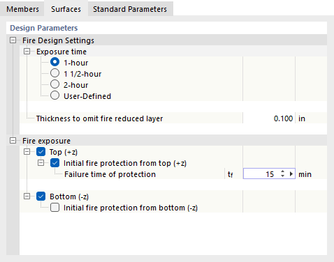
The “Thickness to omit fire reduced layer” defines the minimum thickness of a layer for the design: The layer is only considered if its remaining thickness after charring is greater than the specified value. Thinner residual layers are not considered.
Fire Exposure
Specify which side(s) of the surface are exposed to the fire. The “Top (-z)” surface side is the negative surface side (that is, opposite the local z-axis), and the “Bottom (+z)” surface side is the positive surface side.
Using the “Initial fire protection from top/bottom” check boxes, you can specify whether the surface is protected from fire exposure by certain measures, such as fire protection cladding in the form of gypsum board. If this is the case, specify parameters like the failure time of the fire protection cladding. This describes the point at which the fire exposure becomes effective for the surface.
Standard Parameters
The Standard Parameters tab manages the standard-specific parameters.
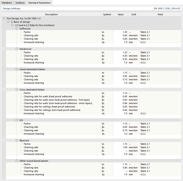

Here you can check the charring rates, coefficients, or adjustment factors and modify them, if necessary.
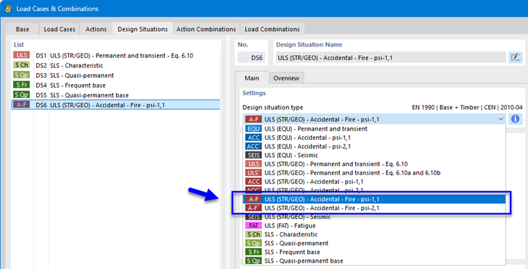
Design Situation for Fire
For fire design, it is necessary to select a design situation type or limit state type labeled Fire on the design page. Otherwise, no fire resistance design will be performed! Therefore, assign the appropriate type in the Design Situations table.
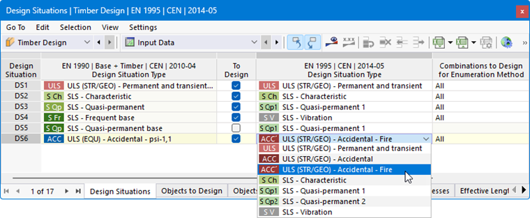
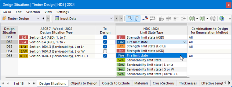
If you have created a design situation for fire in the Load Cases and Combinations dialog box of RFEM 6, the type is preset accordingly.