


This chapter explains how the tensile forces in the individual horizontal stirrups of the bucket are derived from the horizontal forces acting on it. It shows how the forces are composed of direct tensile stress and the bending of the bucket wall and are distributed to the various stirrup groups via strut mechanisms.
Horizontal Forces on Bucket Walls
The first step in the design process is to analyze the distribution of horizontal forces on the individual bucket walls. Depending on whether the contact surface between the support and the bucket is rough or smooth, different components of transferable horizontal forces result. The resulting horizontal forces form the basis for the subsequent determination of the tensile forces in the stirrups.
The design is only carried out for the upper horizontal force, even if the lower force is usually greater, for the following reasons:
- In the bottom area, the end wall is at least partially restrained, based on the vertical reinforcement and the connection to the foundation plate. Therefore, the horizontal force does not act there as it does in the top area.
- The bucket is often thicker at the bottom, which increases the load-bearing capacity and makes the greater lower force less critical.
- The concrete design is carried out for a specified partial width (approx. 1/3 of the wall height), regardless of the total height, which means additional safety.
For a bucket foundation with rough bucket sides, the upper horizontal force is:
|
My |
Design bending moment |
|
d |
Embedment depth of the column |
|
Hx |
Design horizontal force without additional foundation loads |

For a bucket foundation with smooth bucket sides, the upper horizontal force is:

Concrete Design of Bucket Wall Subjected to Bending
Verification of the concrete of the bow-stressed quiver wall
The design is exemplified for the bucket wall in the y-direction, which is stressed by a upper horizontal force Ht,x in the x-direction. The bending thus arises around the y-axis.
The upper horizontal force Ht,x can be split so that half of it acts at each quarter point of the column's length in the y-direction.

If we now consider the upper right corner on its own, for example, this must be in equilibrium:

The moment around the point P is therefore calculated as:
It is necessary to balance the bending design moment MEd with an opposite moment.
This is created by the concrete compressive force on the compressed inner side of the bucket wall in the y-direction with the lever arm z to the rotation point P:

To determine the concrete compression required for this, proceed as follows:
- It is assumed that the concrete stress is distributed evenly across the compression zone.
- Starting with a concrete strain of 0.0 ‰, this is gradually increased until the resulting internal moment corresponds to the bending design moment MEd.
- At the same time, it is assumed that the steel on the external side of the bucket wall has already reached its maximum strain.
As soon as the calculated internal moment is greater than the design bending moment MEd, the iteration is terminated. The bucket wall is then designed for bending and the required reinforcement area of the horizontal stirrups in the bucket due to bending of Ht,x Asw,h,req (MEd|Ht,x) is determined.
External Horizontal Reinforcement
The external stirrup on all sides is subjected to two different stresses:
- Due to bending of the wall perpendicular to the considered horizontal force
- Due to tension in the wall running parallel to the considered horizontal force
The image shows the reinforcement arising due to Ht,x and the corresponding Ht,y.

| Reinforcement | Description |
|---|---|
| Asw,h,out,req(MEdHt,x) | Required reinforcement area of the horizontal outer stirrups in the bucket due to bending of Ht,x |
| Asw,h,req(Ht,x) | Required reinforcement area of the horizontal stirrups in the bucket due to tensile force in the x-direction |
| Asw,h,out,req(MEdHt,y) | Required reinforcement area of the horizontal outer stirrups in the bucket due to bending of Ht,y |
| Asw,h,req(Ht,y) | Required reinforcement area of the horizontal stirrups in the bucket due to tensile force in the y-direction |
The maximum tensile stress on the stirrups is calculated from the sum of the tensile forces resulting from bending and axial tensile force. The required reinforcement is calculated as follows:
Horizontal Reinforcement in y-Direction
In this stirrup, only horizontal forces in the x-direction result in tensile forces. The horizontal force Ht,y does not cause any tensile force here for two reasons:
- No tensile force due to bending in the y-direction: The stirrup leg in the x-direction lies within the compression zone of the wall bent by the horizontal force Ht,y. The stirrup acts here more as compression reinforcement, which is, however, neglected.
- No tensile component due to parallel stirrup legs: The stirrup legs that run parallel to the horizontal force Ht,y transfer their forces to the external bucket side through diagonal compression struts. There, the vertical force is introduced into the vertical stirrup legs. Since the vertical stirrup leg end of the y-outer stirrup is located above this introduction point, no vertical force component from the compression strut arises in this stirrup.

Horizontal Reinforcement in x-Direction
Similarly to the reinforcement in the y-direction, only horizontal forces acting perpendicular to the direction of the stirrup leg result in a tensile force in the stirrup.

Derivation of Tensile Forces in Stirrups from Horizontal Forces
It is necessary to explain how the respective tensile forces in the stirrups, which were then superimposed to form the governing tensile force, arose from the respective horizontal forces. This is illustrated using the horizontal force Ht,x as an example.
Distribution of Horizontal Force to Stirrups
The horizontal force Ht,x is distributed evenly across the four legs of the stirrup acting parallel to the force. Each of these legs therefore has to carry a quarter of the total force:

The required reinforcement for this is determined as:
Bending Effect on Bucket Wall
In addition, Ht,x causes the bucket wall to bend in the y-direction. The resulting concrete compressive force was determined during the concrete design. For the sake of equilibrium, it is necessary to absorb this concrete compressive force by a corresponding tension in the outer stirrups.
Tensile force component in the outer stirrups:
This bending tensile force is not distributed evenly across both horizontal stirrups, but follows the compression strut mechanism.
The struts spread out at an angle θ1.
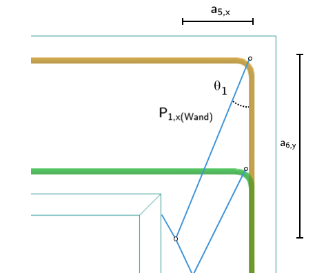
To obtain the tensile force component resulting from the bending of the bucket wall, it is recommended to proceed as follows:
Angle of dispersal within the bucket wall:
where:
|
dx(wall) |
Static effective depth in the wall in the x-direction |
|
kx(wall) |
Ratio for the lever arm of internal forces |
|
xx(wall) |
Used neutral axis depth for the lever arm of internal forces by design |
|
db,y |
Bucket dimension in the y-direction |
|
cy |
Column dimension in the y-direction |
|
c(k) |
Existing concrete cover of the bucket foundation |
|
ds,h |
Diameter of horizontal stirrups in the bucket |
Proportional compressive force in outer stirrups due to the bucket wall bending:
Proportional tensile force in outer stirrups due to the bucket wall bending:
The required reinforcement area of the horizontal outer stirrups in the bucket due to bending of Ht,x is calculated as follows:
The required reinforcement area of the horizontal stirrups in the y-direction in the bucket due to bending of Ht,x then corresponds to the remaining component of the total required reinforcement area after the reinforcement of the outer stirrups Asw,h,out,req (MEd|Ht,x) has been deducted: