This load wizard facilitates the task of placing a surface load on members in the model. This allows you, for example, to apply a snow load to the rafters of a roof plane or a live load to a grillage without having to manually determine the load components of the members.
Main
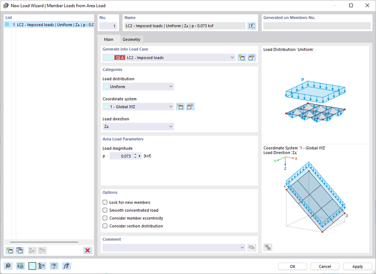
The Main tab manages the load parameters.
Generate into Load Case
In the list, select the load case to which you want to assign the loads. You can use the
![]() button to create a new load case.
button to create a new load case.
Categories
Load Distribution
The list provides various options to determine how the area load acts:
- Uniform: There is a load with a constant magnitude.
- Linear: The load is distributed linearly variable. In the "Area Load Parameters" dialog section, you can specify three reference nodes with respective load values.
- Varying in X / Y / Z: The load is distributed linearly variable in the direction of a global axis. You can define the area load parameters in a separate tab (see the paragraph Varying).
Coordinate System
The area load can act perpendicular to the load plane ("Local z") or in relation to the global XYZ coordinate system. Alternatively, you can select a user-defined coordinate system or create a new one.
Load Direction
If the surface load does not act perpendicular to the load plane, but in the direction of a global axis, the list provides different options.
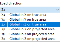
The surface load can be related to the true area (such as a weight load) or the projected area (such as a snow load). The load direction is illustrated in the dialog sketch.
Area Load Parameters
Enter the magnitude of the uniform surface load. If the load is linearly variable, you can define the numbers of three nodes with the assigned loads. You can use the
![]() button to select the nodes graphically in the work window.
button to select the nodes graphically in the work window.
Options
If you select the "Lock for new members" check box, the area load acts only on the currently available members of the area load plane as defined in the "Geometry" tab. Members you add to the area load plane later will get none of the components of the area load.
The "Smooth concentrated load" check box allows you to smooth point loads that may occur in the case of complex geometries in the course of load distribution. Thus, the concentrated loads will be distributed to adjacent members.
The "Consider member eccentricity" option controls how the area load acts on the members of the plane with member eccentricities: If the check box is not selected (default setting), the eccentrically arranged bars are taken into account as normal when determining the load components. If you select the check box, however, these members do not receive any components from the area load.
With the "Consider section distribution" check box, you can control whether the area load resulting from a taper definition also acts on the inclined members (default setting). If you select the check box, the area load is not applied to members in the load plane that have a non-uniform cross-section distribution (see the chapter Section ).
Geometry
In the Geometry tab, you can delimit the load plane and define the load-bearing members.
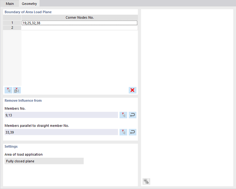
Boundary of Area Load Plane
Define the boundary of the area load plane by clicking the corner nodes of the plane one after the other in the work window. To do so, use this button:
![]() . The plane is marked in the selection color. You can use the
. The plane is marked in the selection color. You can use the
![]() button to select the cells of a plane that RSTAB automatically recognizes in the model.
button to select the cells of a plane that RSTAB automatically recognizes in the model.
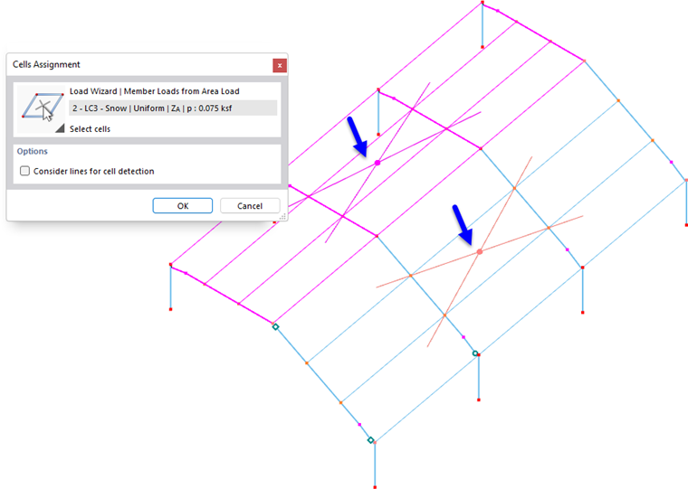
At least three nodes are required to define a plane. The area does not need to be enclosed by members on all sides.
You can define different area load planes, which then appear row by row in the table.
Remove Influence from
This dialog section allows you to exclude members such as bracings or purlins from the load transfer. You can define the members graphically using the
![]() button, either individually or, by using a template member, "parallel" to all load-free members. You can use the
button, either individually or, by using a template member, "parallel" to all load-free members. You can use the
![]() button to import the members of object selections. To do this, select the relevant object selection (OS) in a separate dialog box.
button to import the members of object selections. To do this, select the relevant object selection (OS) in a separate dialog box.
Settings
The "Area of load application" controls how the area load acts in the model:
- Fully closed plane: If there is an area between members that is not displayed in the RSTAB model, the area load of the entire plane is distributed to the members. This way, you can apply, for example, roof or wall loads to a framework.
- Empty, on members only: If the model consists only of members, such as a lattice tower, the load acts only on the member cross-sections. The load is determined taking into account the member position.
Varying
The Varying tab is available if you have selected a variable load distribution in the "Main" tab, which acts in the direction of a global axis.
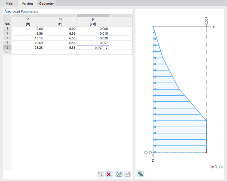
You can define a freely variable load such as a height-dependent wind load. Enter the ordinates or the relative distances, and assign the corresponding load values.
Tolerances
In the Tolerances tab, you can set the criteria by which members and nodes are evaluated as belonging to a plane or line.
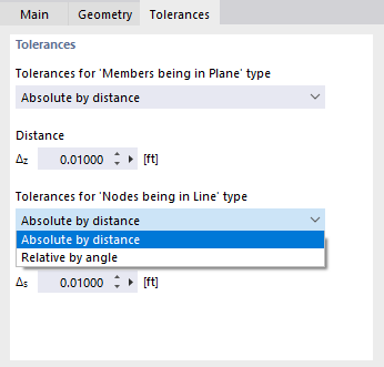
Tolerances for "Members being in Plane" type
Use the list to define whether the permissible deviation of a member from the load plane is to be described as "Absolute by distance" or "Relative by angle". Then, specify the distance Δz or the angle φz. The load generator recognizes cells for all members that lie within the limit and generates corresponding loads.
Tolerances for "Nodes being in Line" type
In the list, you can select whether the permissible deviation of a node from the definition line of the member is to be described as "Absolute by distance" or "Relative by angle". Then, specify the distance Δs or the angle φs.
Displaying Member Loads and Distribution Areas
Once the member loads have been generated, you can display the applied load not only as a distributed load, but also as actual member loads. To do this, use the Display Separately option in the shortcut menu of the area load or activate Loads → Load Wizards → Member Loads from Area Load → Display Separately in the Navigator - Display. You can also use the Display Distribution Areas option in the navigator to visualize the Voronoi cells of the selected load.