


The standardized sections are available in a library for entering cross-sections.

List
The "List" manages all the cross-sections of the model. The List of Object Types table describes the functions with which you can create, copy, or delete objects of a list.
Name
The cross-section's name is automatically specified by the cross-section parameters. However, you can also enter a description in this text box and use it to search for the cross-section in the library. If the description matches an entry in the library, RSECTION imports the stored cross-section properties. To select the cross-section from the library, click the
![]() button at the end of the input line. The transfer of cross-sections is described in the chapter Cross-Section Library.
button at the end of the input line. The transfer of cross-sections is described in the chapter Cross-Section Library.
Main
The Main tab manages the basic section parameters.
Material
It is necessary to assign a material to each cross-section. You can select it from the list of already defined materials. The buttons next to the input text box allow you to select a material from the library or to define a new one (see the chapter Materials).
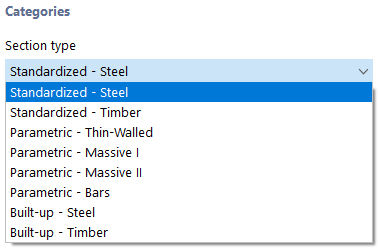
Section Type
For cross-sections from the library, the "cross-section type" is preset according to the usual classifications there (see the chapter Cross-Section Library).
Manufacturing Type
The production method of a cross-section is displayed for the cross-sections from the library.
Sectional areas
The cross-sectional areas are subdivided into the total area "Axial A", and the areas for "Shear Ay" and "Shear Az". The shear area Ay is related to the moment of inertia Iz; the shear area Az is related to Iy accordingly.
For unsymmetric cross-sections, shear areas are displayed around the principal axes u and v of the cross-section.
Moments of inertia
The second moments of area define the section stiffness with regard to loading by moments: The torsional constant IT describes the stiffness against rotation about the longitudinal axis. The second moments of area Iy and Iz describe the stiffnesses against bending about the local axes y and z. Axis y is considered to be the "major" axis. The warping moment of inertia Iω is used to describe the resistance to warping.
For unsymmetric cross-sections, the second moments of area are displayed around the principal axes u and v of the cross-section. The local section axes are shown in the cross-section graphic.
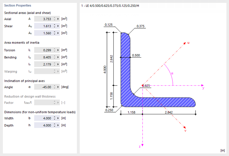
Inclination of principal axes
The inclination of principal axes describes the position of the principal axes in relation to the standard principal axis system of symmetrical cross-sections. For unsymmetrical sections, this is the angle α between the axis y and the axis u (positive in clockwise direction). The principal axes are called y and z for symmetric cross-sections, and u and v for unsymmetric cross-sections (see the image Section Properties and Axes).
The principal axis inclination is determined according to the following equation:
|
α |
Principal axis angle |
|
Iyz |
Biaxial second moment of area |
|
Iz |
Moment of inertia about the z-axis |
|
Iy |
Moment of inertia about the y-axis |
Dimensions (for non-uniform temperature loads)
The dimensions with regard to the width b and height h of the cross-section are required for the calculation of temperature loads.
US notation for section properties
Activate this check box to display the symbols of the cross-section properties in compliance with the US convention.
Section Location / Rotation / Mirroring
In this tab, you can define the position and rotation angle of the cross-section. For unsymmetric cross-sections, this tab also provides options to "Mirror" the cross-section.

Offset Point Location
The offset point of the cross-section is used as a reference point to place the cross-section. This point is highlighted in red in the cross-section graphic. Coordinates y and z refer to the centroid of the section.
You can enter the reference point directly in the text boxes, or define it by clicking one of the blue points in the cross-section graphic.
Section Location
You can enter the insert point of the cross-section into the text boxes directly or using the
![]() button in the work window. The cross-section is placed at the defined offset point at the insert point.
button in the work window. The cross-section is placed at the defined offset point at the insert point.
Rotation About x-Axis
You can rotate the cross-section about a freely selectable angle α.
Mirror
You can mirror unsymmetric cross-sections. To do this, select the corresponding check box.
Hybrid
You can assign different materials to cross-section parts of cross-sections of the "Parametric – Massive II" type.

Stress Points
Stress points are required to determine the stresses acting on the cross-section. All library sections are provided with stress points at the design-relevant locations of the cross-section.
The Stress Points tab consists of up to four sub-tabs containing the coordinates of the stress points, static moments, and warping coordinates with the corresponding thicknesses (only for thin-walled cross-sections) as well as the unit stresses calculated with the thin-walled theory (only for thin-walled cross-sections) and unit stresses calculated with the finite element method.

You can check the cross-section distribution and stress curves in the cross-section graphic: Click in the column of the value or select the type from the list below the graphic.
Convert to Normal Geometry
This function breaks down the cross-section into its individual objects, such as points, lines, elements, parts, and so on. Then, you can edit the individual objects.