


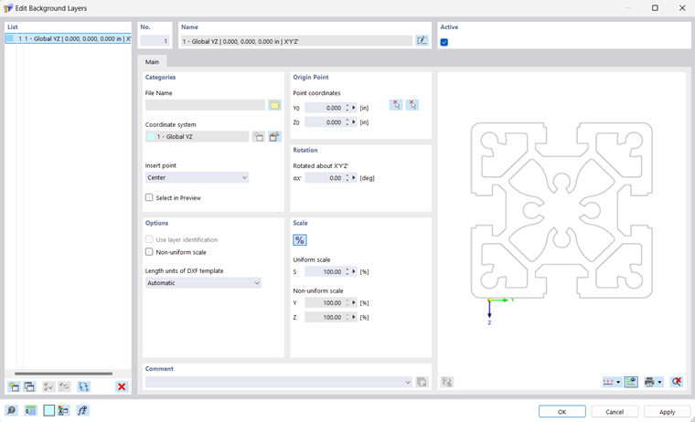
You can use a DXF file as a background layer for entering objects. Compared to the DXF import, where the entire model is converted into points and lines and then imported, background layers represent a kind of transparent sheet for specific modeling.
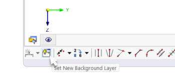
You can also define a new background layer using the
 button available in the CAD toolbar.
Categories
The background layer should be in .dxf format. Set the "File Name" by clicking the
 button to select the file in the Windows dialog box.
An "Insert point" determines the location that is placed on the "envelope" of the background layer at the origin point. Various options are available for selection in the list:
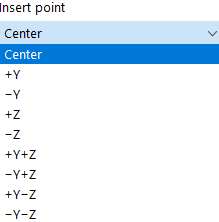
If you select the "Select in Preview" check box, you can define the insert point graphically: To do this, click the
 button in the "Origin Point" section on the right and define the insert point in the preview area.
Origin Point
The insert point of the background layer is placed in the model at the "Origin Point". Enter the coordinates of this point or define it graphically using the
button in the work window on the left or by using the
button in the preview area on the right.
Options
If you want to use a "Non-uniform scale" for scaling the layer in the spatial directions, activate the check box. Thus, the corresponding text boxes in the "Scale" section become accessible.
If you want to import only from some layers, activate the "Use layer identification" first. Then, select the corresponding layers in the "Layer" tab.
If the "Length units of DXF template" are not to be automatically adopted from the DXF file, you can select the appropriate unit from the list.
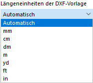
Scale
In this dialog section, you can scale the size of the background layer; for example, to compensate for inconsistencies in units. The normal case is a "Uniform scale" Δ with regular scaling in all directions. For a non-uniform scale, activate the corresponding check box in the "Options" section.
Use the
 button to switch between relative and absolute input.
Using Background Layer
If the background layer is set as Active, it is highlighted in gray. Now, you can place points, lines, elements, and parts at the intersection points of layer lines.