


The geometry of model objects is defined by lines. They are essential for creating parts and openings. When entering parts or openings graphically, the lines are created automatically.
Every line is defined by a start and an end point. To define complex types of lines, intermediate points are required.

The line number is assigned automatically, but it can be changed. The order is irrelevant for the numbering. It does not have to be continuous, either; gaps in the numbering are allowed.
Main
The Main tab manages the most important line parameters.
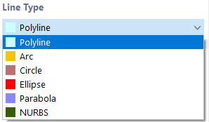
Line Type
Various line types are available for selection in the list.
Single Line / Polyline
Selecting the line entry on the drop-down menu opens the "New Line" dialog box shown in the image "New Line".
A single line is defined by a start point and an end point. It represents a direct connection between both points.
A Polyline is a polygonal chain consisting of several straight line segments. Therefore, the dialog box (see the image "New Line") shows the numbers of the intermediate points in addition to those of the start and end points. For the sake of simplicity, single lines are managed as polylines, too.
When entering them graphically using the
![]() , button, you can select existing points, grid points, or snap objects as definition points. However, you can also set the points freely in the work plane.
, button, you can select existing points, grid points, or snap objects as definition points. However, you can also set the points freely in the work plane.

Arch

An arc is defined by three points. In the "Arc" tab, you can enter the start point P1, the end point P2, and the control point P3, select them graphically, or create a new one. The graphic illustrates the order of the points.
From the three points, RSECTION determines the "arc parameters": the rise h, the radius r, the opening angle α, and the arc center. If you change a parameter, the point coordinates will be adjusted accordingly. When changing the opening angle, you can use the list to define which of the three definition points should be moved.
When defining the arc graphically using the
![]() button, you can select the points or define new points directly in the work window.
button, you can select the points or define new points directly in the work window.

Circle

A circle is defined by its center and the radius. In the "Circle" tab, you can enter or graphically define the coordinates of the circle center and specify the circle radius. The rotation of the circle about the normal defines the control point on the circle line. Its coordinates are given in the last two text boxes.
When defining the circle graphically using the
![]() button, you can define the center and radius in the work window by clicking the corresponding points.
button, you can define the center and radius in the work window by clicking the corresponding points.

Ellipse

To define an ellipse, three points are required. To define the principal axis of the ellipse, you can enter the two points P1 and P2, select them graphically, or define new points in the "Ellipse" tab. The control point P3 describes the length of the minor axis.
Parabola

This line type can be used to create a conic section. Define the two end points of the parabola and the control point in the "Parabola" tab. Based on this information, RSECTION determines the parabola parameters and the focus.
When defining the parabola graphically using the
![]() button, you can define the points by clicking into the work window, or you can redefine them.
button, you can define the points by clicking into the work window, or you can redefine them.

NURBS

NURBS (non-uniform rational B-Splines) allow you to model any curves. NURBS are splines whose control points do not lie on the curve itself.
NURBS can be defined graphically using the
![]() button by defining the control points one by one with a mouse click.
button by defining the control points one by one with a mouse click.

Point on Line
By selecting this point type, the points can be placed on the line without dividing the line (see the image Defining Points on Line ).
Information | Analytical
This section shows the length of the line.