


Elements are required for calculation with the analysis method 'Analysis of thin-walled structures' and for the effective cross-section calculation.
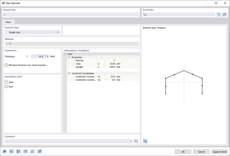
The location of each element is determined by its start and end points. For complex element types, additional intermediate points are required.
Elements can only be connected to each other at their start and end points. If elements cross without sharing a common point, there is no connection.
Elements, with the exception of null elements, must always lie within a part. You must create this part beforehand when entering an element via the dialog. In contrast, the part is generated automatically during graphical input of elements. A part is only considered in the analysis with the 'Analysis of thin-walled structures' method and for the effective cross-section calculation if at least one element lies in this part.
The element number is assigned automatically but can be changed. The order does not matter for the numbering. It does not need to be consecutive; gaps in the numbering are permitted.
Base
The Base tab manages elementary element parameters.
Element type
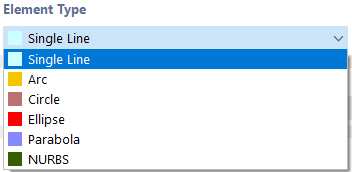
Various element types are available for selection in the list.
Single Line
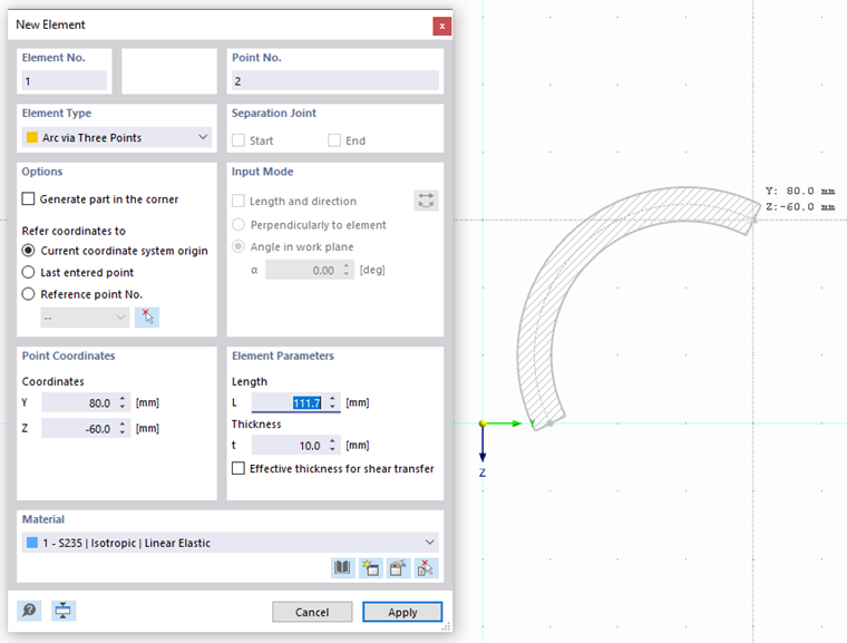
The 'New Element' dialog is shown in the 'New Element' Dialog image.
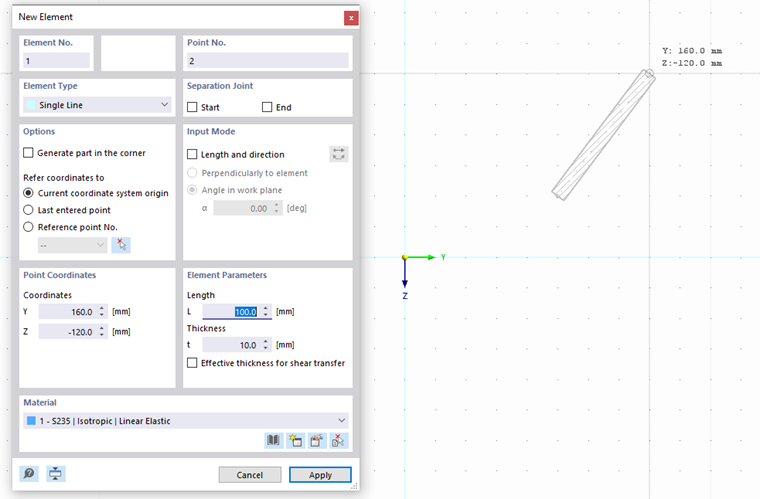
A Single Line is defined by a start point and an end point. It represents the direct connection between the two points.
For graphical input via the
 button, you can select existing points, grid points, or snap objects as definition points. You can also place the points freely in the work plane.
Arc
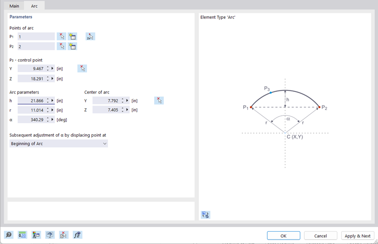
An arc is defined by three points. In the 'Arc' tab, you can enter, graphically select, or create the start point P1, the end point P2, and the control point P3. The graphic illustrates the order of the points.
From the three points, RSECTION determines the 'Arc parameters': rise h, radius r, opening angle α, and arc center point. If you change a parameter, the point coordinates are adjusted accordingly. When changing the opening angle, you can use the list to specify which of the three definition points should be moved.
If you define the arc graphically using the
 button, you can select or place the points directly in the work window.
Circle
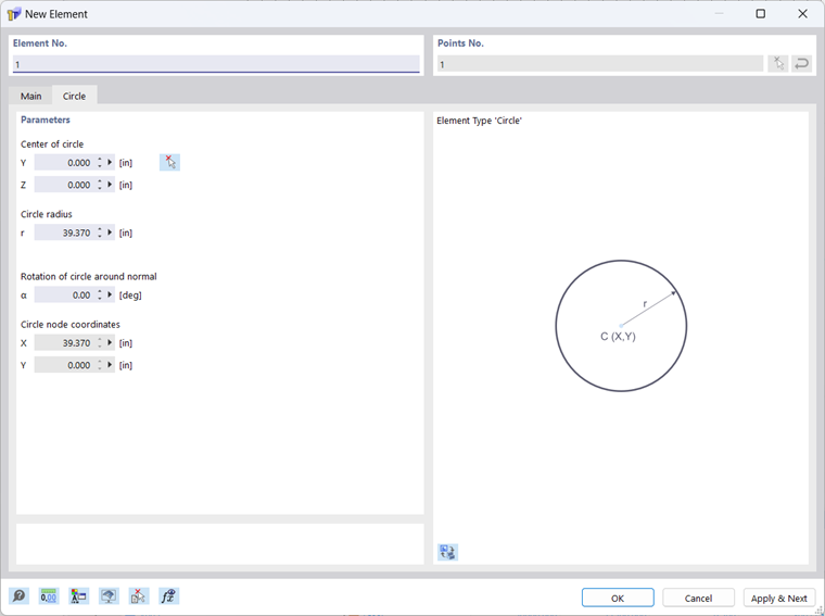
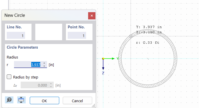
A circle is defined by its center point and the radius. In the 'Circle' tab, you can enter or graphically define the coordinates of the circle center point, and specify the circle radius.
If you define the circle graphically using the
 button, you can define the center point and radius in the work window by clicking the corresponding points.
Ellipse
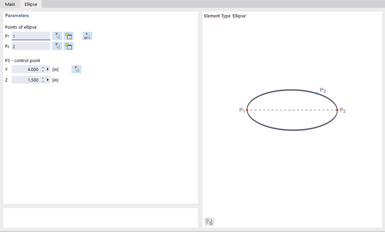
Three points are required to define an ellipse. In the 'Ellipse' tab, you can enter, graphically select, or redefine the two points P1 and P2 to define the major axis of the ellipse. The control point P3 describes the length of the minor axis.
Parabola
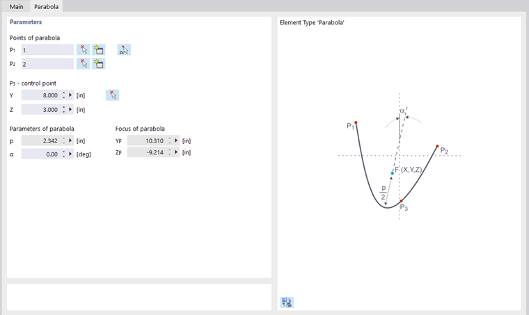
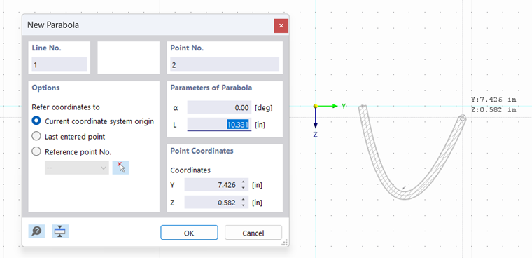
This element type can be used to create a conic section curve. To do this, define the two end points of the parabola and the control point in the 'Parabola' dialog tab. From this information, RSECTION determines the parabola parameters and the focal point.
If you define the parabola graphically using the
 button, you can define or redefine the points in the work window by clicking.
NURBS
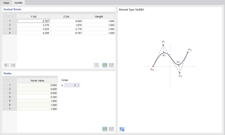
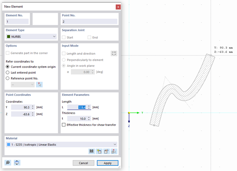
NURBS elements (non-uniform rational B-splines) allow you to model any curved element.
You can define NURBS elements graphically using the
 button by defining the control points one after another with a mouse click.
Material
During graphical input of an element, you can select a material from the list of already created materials, or edit and redefine it. When entering an element via the dialog, the material is taken from the part.
Thickness
The actual thickness of the element is to be defined in this input field.
Effective thickness for shear transfer
The effective thickness for shear transfer corresponds by default to the thickness of the element. If you activate the check box, you can set a thickness for shear transfer that differs from the actual thickness.
Separation joint
You can use a separation joint to separate individual elements from each other at their connection point. You can define this separation joint both at the beginning and at the end of an element. Separation joints are only available for elements of the 'Single Line' type. They are important so that, in the case of welded joints, forces are only transferred via the welds – and not directly through the adjacent elements themselves.
Information | Analytical
This section provides an overview of important element properties such as surface and length.