Stirrups are used to absorb shear and torsional forces in concrete components.

The stirrup number is assigned automatically, but it can be changed. The numbering order is irrelevant. It also does not have to be consecutive; gaps in the numbering are permitted.
Cover Points No.
You can position stirrups at cover points. Cover points are points of type 'On Line' on the cover line. You can also create additional cover points on the cover line and use them for the stirrup arrangement.
For the 'Standard' stirrup type, both open and closed stirrups can be defined. A closed stirrup is created when the starting cover point is identical to the ending cover point. To do this, specify the starting cover point again at the end of the point sequence. For example, specifying the cover points 504–501,504 creates a closed stirrup, since the starting cover point 504 is also the ending cover point 504.
Stirrup Type
Various stirrup types are available for selection in the list.

Standard
The 'Standard' stirrup type allows the definition of any stirrup shapes, including rectangular, circular, and triangular stirrups as well as stirrups with straight and curved segments.
To create a stirrup, specify the desired cover points. The resulting stirrup segments are listed in the 'Segments' tab and can be edited there.

For each segment, you can adjust the associated cover points, change the segment type, and, for segments of the 'Arc' type, additionally edit the control point coordinates.
In addition, segments can be split, merged, or deleted. Use the buttons below the list for this.
- table.uni#
width=10%|width=60%
 |Splits selected straight stirrup segments
 |Merges selected straight stirrup segments
 |Deletes the selected segments
- /
Circle
The 'Circle' stirrup type is used for the quick and easy definition of circular stirrups.

Various options are available for defining a circular stirrup. You can define the circular stirrup directly using the circle center point and the radius. Alternatively, you can specify one or two cover points as well as the circle center point; in this case, the radius is calculated. You can also specify three cover points. The circle center point and the radius are then determined from the cover points.
Material
In the list of materials that have already been created, you can select a material for the stirrup, edit it, or define a new one. Only materials of the 'Reinforcing steel' type are permitted.
Parameters
The available parameters depend on the selected stirrup type. For the 'Standard' stirrup type, the stirrup diameter ds,st, the stirrup diameter of curvature dbr,st, and the mandrel diameter factor k are interdependent. The relationship is described in the following equation:
dbr,st = k · ds,st
Information | Analytical
This section provides an overview of important properties such as the reinforcement area, length, and weight of the stirrup.
Equivalent Thin-Walled Section (ETWS)
In addition to the reinforcement area, length, and weight, the stirrups also define the geometry of the equivalent thin-walled section. From the closed stirrups, the program determines the equivalent thin-walled section, which is used in the Concrete Design add-on of RFEM 6 and RSTAB 9 for the torsion design.
The following image shows a box girder cross-section with stirrups and the equivalent thin-walled section derived from them.
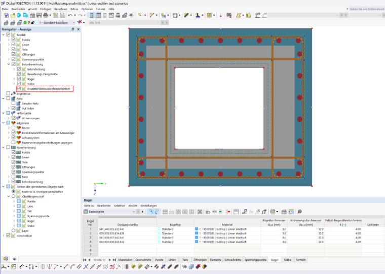
Creation of the Equivalent Thin-Walled Section
Each closed stirrup forms its own equivalent thin-walled section. A stirrup of the Standard type is closed when the starting cover point is identical to the ending cover point (see the Cover Points No. section). Open stirrups do not form an equivalent thin-walled section.
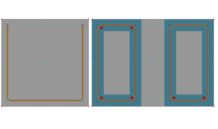
The center line of the equivalent thin-walled section runs through the middle of the stirrup bar. The effective wall thickness tef is not determined in RSECTION, but in the Concrete Design add-on according to the selected standard.
Rules
The following rules apply when creating the equivalent thin-walled section:
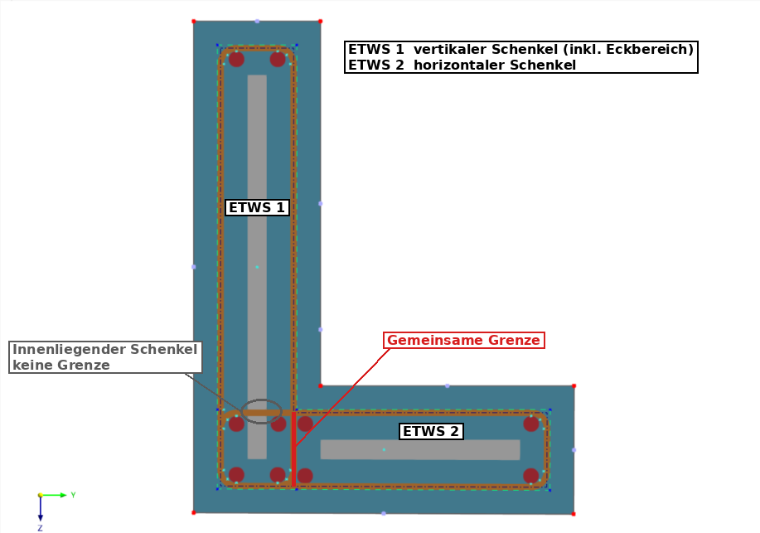
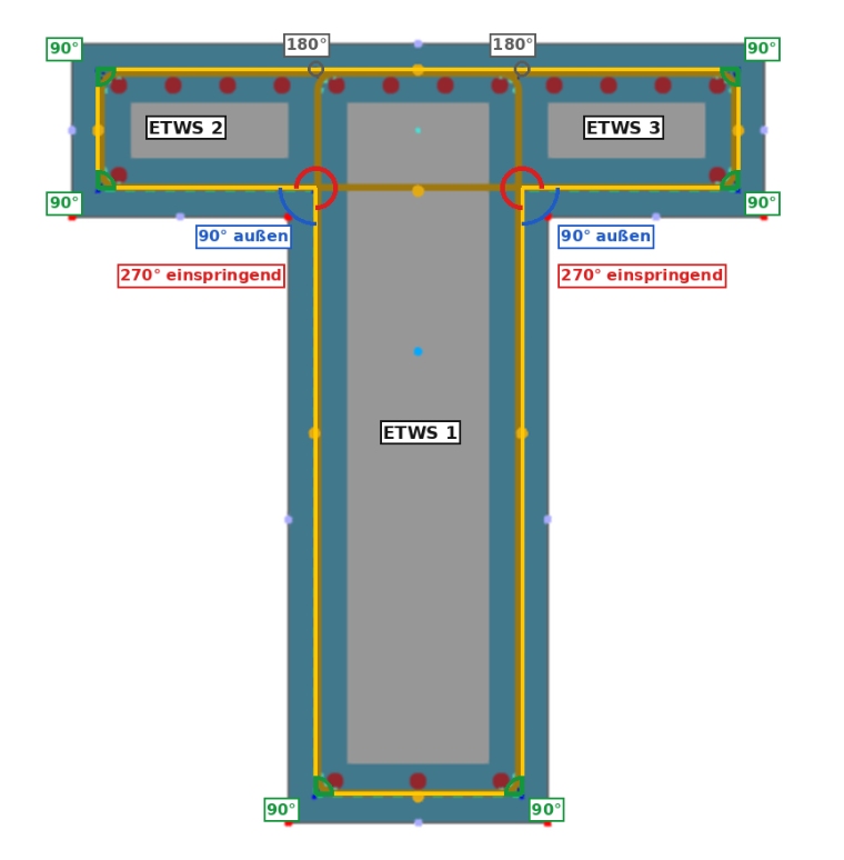
- Convex shape: An equivalent thin-walled section must be convex, that is, all interior angles of its edge are less than or equal to 180°. If the outer edge of the union has a recessed corner, it is divided into several equivalent thin-walled sections at this point.
- Intersecting stirrups: If a recessed corner is created at an intersection of two stirrups, the larger area cuts off the smaller one. The stirrup leg at this point forms the common limit of the two