


The stresses of a cross-section are calculated at stress points and displayed in tables. The stress points are generated automatically, but you can also define them manually.

Main
The Main tab manages the most important stress point parameters.
Stress Point Type
Various types of stress points are available in the list.
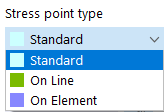
Standard
You can place the stress points of the "Standard" type anywhere in the cross-section.
On Line
You can define stress points of the "On Line" type on lines. The line and the distance need to be defined in another tab.

On Element
You can place the stress points of the "On Element" type on elements. It is necessary to define the element, the element side, and the distance in another tab.

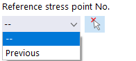
Reference Stress Point No.
These coordinates usually refer to the origin of the global coordinate system (entry "--"). It is also possible to define the coordinates in relation to another stress point. This is useful, for example, to place the stress point at a distance from a defined position. For this, you can use the "Previous" option in the list. You can also enter the reference point directly or select it in the model using
![]() .
.
Part No.
Enter the number of the part where the stress point lies.
Element No.
Specify the number of the element where the stress point lies.
Coordinate Type
The coordinates of a stress point always refer to a coordinate system that describes the position of the stress point in the workspace. The coordinate system is right-hand oriented. In the case of the Cartesian coordinate system, the axes Y and Z describe a translational expansion (linear). Both coordinate directions are equal.
Coordinates
The position of the stress point can be described by its coordinates Y and Z.