


The geometry of the model is defined by points. They are essential for creating lines, and thus elements, parts, and openings. When entering elements, parts, or openings graphically, the points are created automatically.

The point number is assigned automatically, but it can be changed. The order is irrelevant for the numbering. It does not have to be continuous, either; gaps in the numbering are allowed.
Main
The Main tab manages the most important point parameters.
Point Type
Various point types are available in the list.
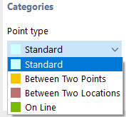
Standard
This type of point is used most frequently. Standard points can be placed graphically in the work plane or anywhere in the workspace by specifying coordinates. When entering lines, parts, or elements graphically, standard points are created as well. Standard points are displayed in red in the model.
Between Two Points
The point rests on the connection line existing between two other points. It is necessary to define the reference points and the distance in another tab.

Between Two Locations
The point rests on the connection line between any two locations. It is necessary to define the locations and the distance in another tab.

On Line
In the case of this point type, a line is not divided into two lines, but remains complete. The line and the distance need to be defined in another tab.

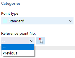
Reference Point
These coordinates usually refer to the origin of the global coordinate system (entry "--"). It is also possible to define the coordinates in relation to another point. This is useful, for example, to place the point at a distance from a defined position. For this, you can use the "Previous" option in the list. You can also enter the reference node directly or select it in the model using
![]() .
.
Coordinate Type
The coordinates of a point always refer to a coordinate system that describes the position of the point in the workspace. The coordinate system is right-hand oriented. In the case of the Cartesian coordinate system, axes Y and Z describe a translational expansion (linear). Both coordinate directions are equal.
Coordinates
The position of the point can be described by its coordinates Y and Z.
Setting Points Graphically
If you open the "New Point" dialog box using the
![]() button, you can set the points directly clicking into the work plane.
button, you can set the points directly clicking into the work plane.
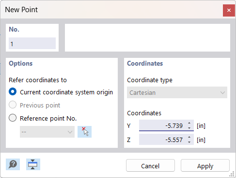
The points are usually snapped to the grid points that are aligned with the current coordinate system. If you enter the coordinates manually in the dialog box, you can apply them with Apply. However, make sure to leave the pointer within the dialog box so that your entry is not overwritten by a new position.