


Dimensions make an important contribution to understanding the model. Various types of dimensioning are possible, which you can apply in a custom manner.

Using the functions of the button
![]() in the CAD toolbar, you can place dimensions directly on the model.
in the CAD toolbar, you can place dimensions directly on the model.
Define the parameters in the 'New Dimension' dialog box. Then click the dimension-defining objects in the work window.

Basis
In the Basis tab, define which type of dimension is involved and how it is to be designed.
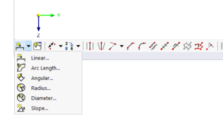
Dimension Type and Style
Various 'dimension types' are available in the list. They correspond to the functions of the buttons (see image Buttons for Dimensions).
| Linear | Length(s) between two or more points |
| Arc length | Length between the points of an arc |
| Angle | Angle between three points or between two lines |
| Radius | Circle or arc radius |
| Diameter | Circle or arc diameter |
| Slope | Slope angle between a line and a plane |
The 'display properties' control which dimension symbols and font are used to display the dimension. You can check the current 'style' using the
![]() button: The 'Display Properties' dialog box appears with a preview of the dimension. There, you can adjust the style for the individual dimension types if necessary.
button: The 'Display Properties' dialog box appears with a preview of the dimension. There, you can adjust the style for the individual dimension types if necessary.
Options
You can supplement the dimension with a dimension symbol. Enter the 'symbol' or select the appropriate entry in the list.

=== Parameters === For length dimensions, you can define the reference parameters in this section. With the 'dimension reference', you can control whether the dimension refers to the true length between the definition points or the projection in one of the global directions. === Offset === The 'dimension line offset' Δ describes the distance of the dimension line from the reference objects. In the button dialog box, you can define this distance graphically (see step (6) in image [[#image032665 Place Dimension Graphically]]). If you activate the 'Offset to global axes' checkbox, you can define the distance of the dimension line with global coordinate reference. == Position == The '''Position''' tab manages the dimension-defining objects and parameters. === Dimension References === The input options in this section depend on the dimension type. For length dimensions, the reference objects are managed in a table: In the 'Type' column, define the type of reference object. Then enter the 'Number' of the point. If the input field is active, you can also define the reference object graphically using the


