


The model can be designed by load case using several internal forces available at the individual locations x along a member.
If there are different internal force conditions, you can design them
- individually in different load cases,
- on different members in the same load case, or
- at different locations x in the same load case.

The internal force number is assigned automatically, but can be changed. The order is irrelevant for the numbering. It does not have to be continuous, either; gaps in the numbering are allowed.
Load Case
From the list, select the load case for which you want to define the internal forces.
Member No.
The internal forces are managed by member. You can freely select the number of a member on which the internal forces act.
Internal Forces Relative to
In the list, select whether the internal forces refer to the principal axes u and v of the model, or to the input axes y and z that lie parallel to the global axes Y and Z in the center of gravity.
Location
Enter the location of the member where the internal forces defined below occur. The entry of internal forces does not need to be linked to a specific location of the structure. You can imagine different combinations of internal forces for the x-locations for which the model is analyzed.
Internal Forces
The image Vorzeichenkonvention für Schnittgrößen am positiven Schnittufer shows the sign convention for positive internal forces in RSECTION.
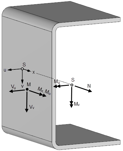
Axial Force
The program considers the axial forces N as acting on the centroid S of the model.
The tension force is positive; the compression force is negative.
Shear Forces
The program considers shear forces Vy, Vz, or Vu, Vv as acting on the shear center M of the model.
If you have entered the shear forces in relation to the input axes y and z, they are automatically transformed in the direction of the principal axes u and v for the calculation. In the "Internal Forces" table, the transformed shear forces are also shown after the calculation.
Torsional Moments
The primary torsional moments Mxp and the secondary torsional moments Mxs are related to the shear center M.
Sum of Torsional Moments
The sum of the torsional moments Mt results from the addition of the primary and secondary torsional moments.
Bending Moments
The program considers the bending moments My, Mz, or Mu, Mv as acting on the centroid S of the model.
If you have entered the bending moments in relation to the input axes y and z, they are automatically transformed in the direction of the principal axes u and v for the calculation.
Bimoment
The program considers the bimoments Mω as acting on the shear center M of the model.