


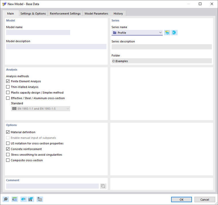
The Main tab manages the basic model parameters.
Model
It is necessary to specify the "Model name", as it is also the file name of the model. However, the "Model description" is optional. It allows you to briefly describe the model. The description appears in the printout report, but has no other function, such as the description of the series.

Series
In the "Series name" list, select the project folder where you want to create the model. You can also use the
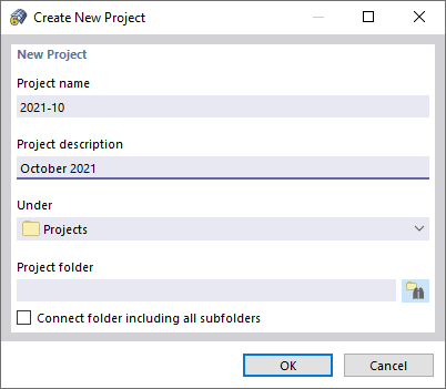
 button to create a new project. The "Create New Project" dialog box appears where you enter relevant project data.
Use the
 button to open the Dlubal Center. There you can set a different project than the current one (see the chapter
Models
).
button to open the Dlubal Center. There you can set a different project than the current one (see the chapter
Models
).
The "Series description" and the "Folder" of the selected project are displayed for information.
Analysis
Activate the check boxes for the analysis methods you want to use for the calculation. The following methods are available:
- Thin-walled analysis
- Finite element analysis
You can select one or both analysis methods at the same time.
Select the "Plastic capacity design | Simplex method" check box to analyze the plastic cross-section resistance, taking into account the interaction of internal forces.
Check the “Effective Cross-Section / Steel / Aluminum Cross-Section” check box to determine the effective cross-section according to the relevant standards. You can select one of the following standards:
- EN 1993-1-1 and EN 1993-1-5
- EN 1993-1-3 (cold-formed)
- EN 1999-1-1 (aluminum)
In the Settings & Options tab, you can specify further detailed settings.
Options
In this dialog section, you define the basic settings for the calculation.
Material Definition
This check box allows you to control whether material input is required for the cross-section. It is necessary to select this check box for the calculation of the effective cross-section or for defining the concrete reinforcement.
Manual Entry of Subpanels
To determine the effective cross-section according to EN 1993-1-1 in conjunction with EN 1993-1-5, EN 1993-1-3, or EN 1999-1-1, it is necessary to define the subpanels of the cross-section. These are typically derived automatically from the cross-section geometry. By selecting the option “Enable manual input of subpanels,” the subpanels can be user-defined. Editing is performed in the “Subpanels” table under “Special Objects” or via the “Edit Subpanel” and “New Subpanel” dialog boxes.
US Notation for Section Properties
Activate this check box to display the symbols of the cross-section properties in compliance with the US convention.
Concrete Reinforcement
Use this check box to control whether to define concrete reinforcement.
Composite Cross-Section
Check this check box to define a composite cross-section allowing you to specify how the individual parts are connected using Connectors.
Stress Smoothing to Avoid Singularities
Select the check box to smooth the stress peaks.
Comment
Here, you can enter text to add a comment to the model. This comment also appears in the printout report.