


Longitudinal reinforcement absorbs the flexural tensile stresses in the longitudinal direction of the member’s main load-bearing direction.
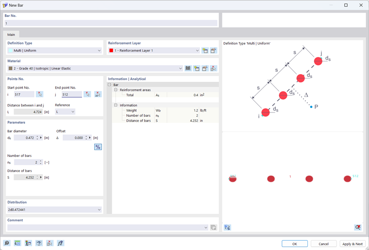
The bar number is assigned automatically, but can be changed. The sequence is irrelevant for numbering. It also does not have to be consecutive; gaps in the numbering are permitted.
Definition type
Various definition types are available in the list:
| Definition type | Description |
|---|---|
| Multiple | Uniform | Several evenly distributed bars on the connecting line between start point i and end point j |
| Multiple | Variable | Several bars on the connecting line between start point i and end point j with definable spacings |
| Multiple | Circle | Several evenly distributed bars on the circle with center P and radius r from the distance between start point i and the center |
| Multiple | Arc | Several evenly distributed bars on the circular arc defined by start point i, end point j, and control point |
| Single | Between two points | Single bar on the connecting line between start point i and end point j |
| Single | Point | Single bar at point i |
Layer
Layers offer you an additional way to structure bars.
To create a new layer, use button
 or select 'New Layer...' from the combo box.
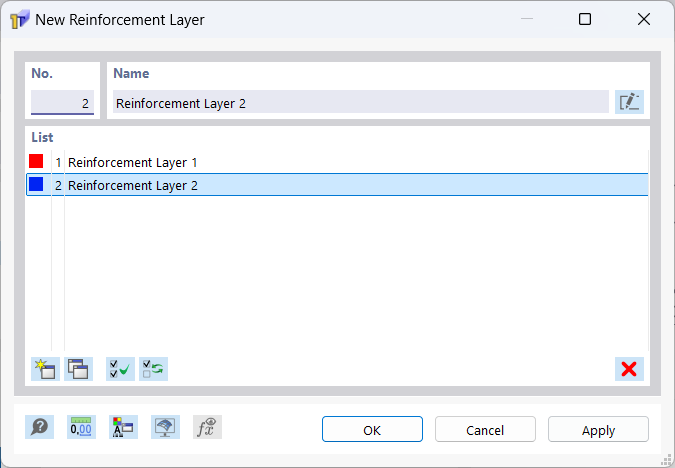
The number and name of the layer are assigned automatically, but can be changed. You can change the color of the layer in the display properties, which you can open via button
 .
.
You can copy selected layers using button
 and delete them using button
 . Only layers that do not contain any bars can be deleted.
Material
In the list of already created materials, you can select a material for the longitudinal reinforcement or edit and redefine it. Only materials of the 'Reinforcing Steel' type are permitted.
Points No.
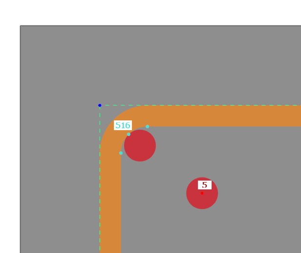
The definition type 'Single | Point' requires only the selection of a single point. The bar is placed at reinforcement catcher points on the outer contour of the stirrup and at all other points at its centroid.
The definition types 'Multiple | Uniform', 'Multiple | Variable', and 'Single | Between two points' require specifying two points. The bars are placed at their centroid on the connecting line between the two points. The distance L between the points is calculated automatically. With the 'Reference', you can control whether the length refers to the actual length L between the points or to the projection in one of the global directions Y, Z.
The definition type 'Multiple | Circle' requires specifying a start point i as well as the center of the circle. The bars are placed with their centroid on the circle defined by the start point and center.
The definition type 'Multiple | Arc' requires specifying a start point i, an end point j, and a control point. The bars are placed with their centroid on the circular arc defined by the start point, end point, and control point.
Parameters
Define the bar diameter ds of the longitudinal reinforcement.
You can also define an offset of the bars. Enter negative values to offset the bar in the other direction.
For the definition types 'Multiple | Uniform', 'Multiple | Variable', 'Multiple | Circle', or 'Multiple | Arc', enter the number ns of bars.
The bar spacing S is calculated for the definition type 'Multiple | Uniform' from the distance L between start point i and end point j and from the number ns of bars.
For the definition type 'Multiple | Circle', the bar spacing S results from the circumference of the circle divided by the number ns of bars.
For the definition type 'Multiple | Arc', the bar spacing S results from the arc length divided by the number ns of bars.
For the definition type 'Multiple | Variable', you can optionally specify the spacings Si and Sn or Sj and Sn. The spacing Sj or Si is then calculated from the number ns of bars and the defined spacings Si and Sn or Sj and Sn. Here, Si denotes the distance of the first bar from start point i, Sj the distance of the last bar from end point j, and Sn the spacing between the bars.
For the definition type 'Single | Between two points', you can either enter the distance Xi-k to start point i or the distance Xj-k to end point j directly in the text fields. Alternatively, you can select the distance in the working window with
 in the working window. With button
 , you can switch between relative and absolute input of the distance. You can reverse the values with button
 .
.
Distribution
The distribution results from the defined bar parameters. However, you can also enter these directly into the combo box. The parameters are then adjusted accordingly. The table below shows the syntax to be observed depending on the definition type. For the definition type 'Single | Between two points', you can enter the spacing relatively or absolutely. For absolute input, simply omit the percent sign.
| Definition type | Syntax | Example |
|---|---|---|
| Multiple | Uniform | [ns]d[ds] | [Δ] | 4d15 | 50 |
| Multiple | Variable | [Si] [ns]d[ds]/[Sn] | [Δ] [ns]d[ds]/[Sn] [Sj] | [Δ] | 50 2d15/100 | 50 2d15/100 50 | 50 |
| Multiple | Circle | [ns]d[ds] | [Δ] | 4d15 | 50 |
| Multiple | Arc | [ns]d[ds] | [Δ] | 4d15 | 50 |
| Single | Between two points | [Xi‑k]% d[ds] | [Δ] d[ds] [Xj‑k]% | [Δ] | 20% d15 | 50 d15 80% | 50 |
| Single | Point | d[ds] | d15 |
Information | Analytical
This section provides an overview of important properties such as reinforcement area, weight, number, and spacing of the bars.