


Welds are used to connect two elements of the “Single Line” type and to determine weld stresses resulting from shear forces and torsion.

The weld seam number is assigned automatically, but can be changed. The order is irrelevant for the numbering. It does not have to be continuous, either; gaps in the numbering are allowed.
Weld Parameters
Various weld types are available for selection in the list.
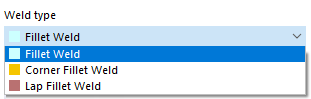
Fillet Weld
A fillet weld is a weld seam where two elements are welded together at an angle.

By defining the first and second elements, you specify the elements to be connected with the fillet weld. The elements can also be elements without thickness (called null elements). The angle between the two elements must be in the range from 45° to 135°, and the elements must be connected directly by a common start or end point.
To ensure that the force transmission is carried out exclusively through the weld and not through the adjacent elements, it is necessary to define a
separation joint
.
The fillet weld thickness represents the root dimension.
Corner Fillet Weld
A corner fillet weld is a fillet weld that connects the edges of two elements on top of each other. The weld runs along the outer longitudinal side (edge) of the elements.

By defining the first and second elements, you specify the elements to be connected with the corner fillet weld. The angle between these two elements must be between 45° and 135°. Both elements must have a positive element thickness – elements without a thickness (null elements) are not allowed. The elements also have to touch each other in at least one location. The contact can also be on an element edge. The elements do not have to be directly connected to each other. The connection is then created by means of a weld.
The fillet weld thickness represents the root dimension.
Lap Fillet Weld
A lap fillet weld is a welded joint where two elements are connected to each other by lap with the weld running along the overlap.

By defining the first and second elements, you specify the elements to be connected with the lap fillet weld. Both elements must have a positive element thickness – elements without a thickness (null elements) are not allowed. Furthermore, the elements have to be parallel to each other and touch each other in at least one location. The elements do not have to be directly connected to each other. The connection is then created by means of a weld.
You can place the lap fillet weld at the start or end of the first element. To do this, select the corresponding weld position.
The fillet weld thickness represents the root dimension.
Properties According to EN 1999-1-1
This check box is only accessible if you have selected the EN 1999‑1‑1 standard in the Main tab.
The calculation of the effective cross-section to consider the strength reduction in the heat-affected zone (HAZ) due to longitudinal welds is still in progress.
Number of heat paths
In this dialog section, you can define the number of heat paths. For fillet welds, a number of heat dissipation paths that deviates from one in three affects the HAZ expansion. The corresponding regulation can be found in EN 1999-1-1, Sections 6.1.6.3(5) and 6.1.6.3(8).
Temperature of material between welding cycles
In this section, you can define the interlayer temperature. When multi-layer weld seams are used, a temperature increase may occur between the layers. This leads to an increase in HAZ expansion at interlayer temperatures above 60 °C. More information can be found in EN 1999-1-1, Section 6.1.6.3(8).