Mouse
The mouse functions follow the Windows standards.
Left Mouse Button
When you click a structure or load object with the left mouse button, you select it. Double-click the object to open the editing dialog box. You can use this functionality not only for the graphic objects in the work window, but also for the object entries in the navigator.
When holding down the Ctrl key, you can select several objects by clicking one after the other. A plus symbol appears on the pointer. You can remove an object from the selection by holding down the Shift key. Accordingly, a minus symbol appears on the pointer.
Right Mouse Button
By right-clicking an object, you open its shortcut menu. It offers object-related commands and functions (see the image Shortcut Menu of Node). Shortcut menus are available not only in the graphics, but also in the navigator and tables.
By holding down the right mouse button, you can open a zoom window to enlarge a certain window area. This corresponds to the "Zoom with Window" function in RSTAB 8.
Scroll Wheel
When scrolling with the mouse wheel, you can maximize or minimize the displayed model. The current pointer position serves as the center of the zoom area. This also works with the "touchpad" by moving two fingers apart or together, or moving two adjacent fingers up or down.
You can move the model using the pressed scroll wheel. When you additionally hold down the Ctrl key, you can rotate the model's view. Rotating is also possible using the scroll wheel and holding down the right mouse button.
ViewCube
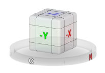
At the top right of the workspace you can see a cube, the ViewCube. By clicking or rotating the cube (hold down the left mouse key while moving the pointer), you can control the view.
View Buttons
It is easy to switch quickly between the default views using the functions in the menu View → Select View and the assigned buttons in the toolbar.
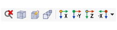
The buttons have the following functions:
| Button | Function |
|---|---|

|
Cancel the zoomed view and show the entire model |

|
Show the model in an axonometric view |

|
Show the model from the viewing angle of the user-defined viewpoint |

|
Show the model in a perspective view |

|
Show the model view in the X-direction |

|
Show the model view in the opposite Y-direction |

|
Show the model view in the Z-direction |

|
Show the model view in the opposite X-direction |
Keyboard Shortcuts
You can also use the keyboard to control the graphics. The shortcuts are available in the "Customize" dialog box, which you can open by selecting Customize Menus and Toolbars in the View menu. Then, select the View category.
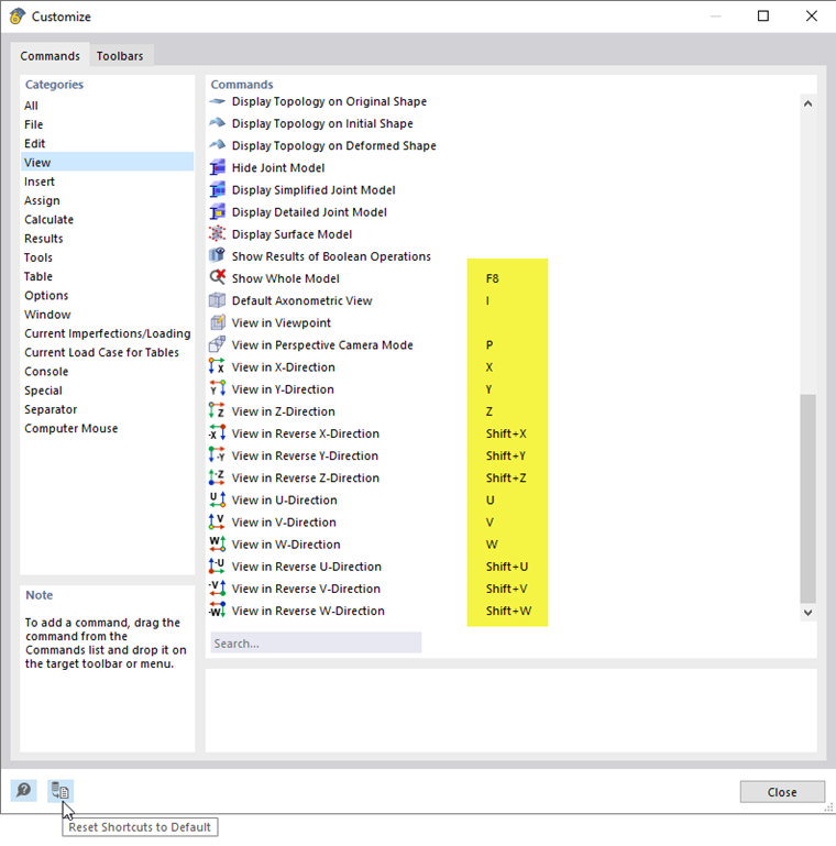
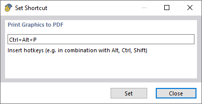
To assign a keyboard shortcut individually, double-click the command. You can then define the key combination in the 'Set Shortcut' dialog box.
You can use the
 button to restore the default shortcuts.
Rendering
There are several ways to graphically represent the model. Use the list button to quickly switch between the three basic display types.
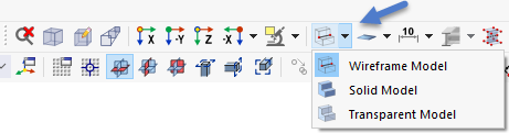
The functions of the buttons are as follows:
| Button | Function |
|---|---|

|
Display a line model of member cross-sections |

|
Display a rendered model in transparent view with member cross-sections |

|
Display the rendered model as a solid model with filled cross-sections where it is not possible to "grab through" it for selection |