


Sections as guide objects allow you to create planar or box-shaped sections through the structural model. They are useful for analyzing partial areas, checking load distributions, or displaying the results for specific planes. They are also very practical for creating plan and detail views for drawing sheets.
Active
The check box in the upper-right section controls whether the section is enabled and active in the work window. You can also use the
 button to enable the new (or selected) section for display.
Categories
In this section, you specify the section type and define the parameters.
Section Type
There are two different types of sections that can be created. Select the relevant entry from the list.
| Section Type | Description |
|---|---|
| Simple plane | Section plane in the model |
| Box | Rectangular “box” in an area of the model |
The other parameters are adjusted to the section and definition types.
Definition Type
The list provides several options for geometrically describing the section plane or the box.
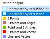
If you align the section parallel to the plane of a coordinate system, the center of the section or box is automatically placed at the center of the model on that plane. In the case of the definition using points, angles, or vectors, you specify the center of the section plane with the first point. For a box, the center of the box is automatically placed at the center of the model in that area.
You can specify the point coordinates or rotation angles in the sections on the right. The
 button allows you to define the points graphically in the work window.
Parallel to
This category appears when the section is defined in a plane of the coordinate system. Use the list to select the plane in the global or user-defined coordinate system to which the section plane is parallel.
Direction
The direction determines whether the section is arranged positively or negatively relative to the plane or base plane of the box. Depending on the setting, the objects are displayed above or below the section. The display is also affected by the setting in the “Model Display” category.
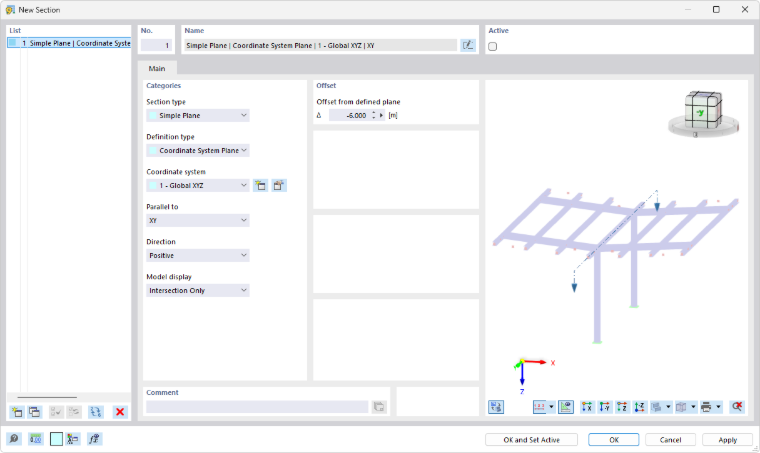
The direction is determined by the orientation of the axis perpendicular to the plane. You can check the section direction by activating the model preview in the dialog graphic using the
 button (see the image New Section).
Model Display
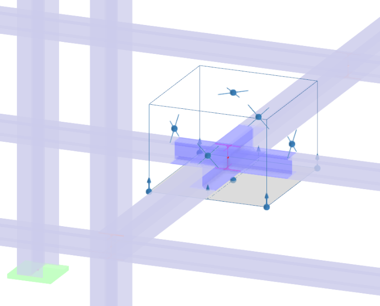
In the list, you can specify which objects in the model are included in the section.
| Model Display | Description |
|---|---|
| Intersection |
|
| Clipped by section |
|
| Full model |
|
Offset
In the section on the right, you specify the distance of the section from the reference plane. For a simple plane, this is the plane of the global or local coordinate system; for a box, it is the base plane of the rectangular box.
Example: Defining Box
The following procedure is recommended for creating a section in the form of a box:
- Open the New Section dialog box.
- Select the Box section type.
- Check that the model display option Clipped by Section is selected by default.
- Specify the definition type (for this example: 3 Points).
- In the Origin Point section, click the
 button on the right.
- In the work window, define the planar base of the box by clicking three points one by one on that plane.
- In the dialog box, click the
button.
- In the work window, you can now drag the area with the grip points to adjust the shape.
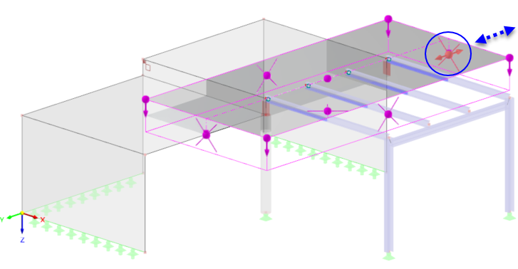
The grip points have the following functions:

|
Corners: Change the box height in the positive or negative direction (up/down) |

|
Centers: Change the box size in the directions of the plane (left/right, front/back) |