The nonlinear material behavior of reinforced concrete, concrete, and steel fiber-reinforced concrete can be modeled using the “Anisotropic | Damage” and “Isotropic | Damage” material models.
Stress-strain Diagram Not Antimetric
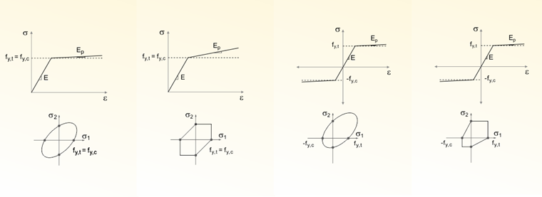
Unlike other material models, the stress-strain diagram for the “Isotropic | Damage” and “Anisotropic | Damage” models is not antimetric to the origin. These models can therefore represent the different behavior of concrete and reinforced concrete under compression and tension.
Crack Formation – Smeared Crack Model
The models can also represent the continuous degradation of the material's stiffness as a result of crack formation. A smeared crack model is used for this purpose. The following image schematically illustrates the possibilities of discrete (a) and smeared (b) crack modeling.
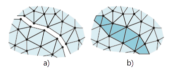
The basic idea behind these models is to determine the strain state additively from a strain of the base material and a crack strain. If a crack occurs, it is assumed that the base material continues to behave elastically and that all additional strains occur in the crack. The modeling of the crack is not done individually, but rather as damage distributed across the element, known as “smeared” damage.
Damage Parameter
The difference between the two models lies in the type of stiffness reduction.
- In the “Isotropic | Damage” material model, this is done using a scalar damage parameter.
- In the “Anisotropic | Damage” material model, on the other hand, the stiffness reduction is performed element by element using a damage tensor.
Isotropic | Damage
Direction-Independent Degradation
Isotropic damage to concrete is characterized by direction-independent degradation of the material stiffness. The stiffness is reduced equally in all spatial directions using a scalar damage parameter, as is typical for simple continuum damage models (Mazars damage model).
The direction of the principal stresses is not taken into account; instead, damage occurs in the direction of the comparative strain, which also includes the third direction perpendicular to the plane. The tension and compression areas of the stress tensor are treated separately. Different damage parameters apply in each case.
The “reference element size” controls how the strain in the crack area is scaled to the length of the element. With the default value of zero, no scaling takes place. This realistically models the material behavior of steel fiber-reinforced concrete.
Anisotropic | Damage
Direction-Dependent Degradation
The anisotropic damage to concrete is characterized by a direction-dependent reduction in material stiffness and is described using a damage tensor. This allows for the representation of different stiffnesses in the tension, compressive, and shear directions.
Physically, the cracks act as discontinuous weak zones with preferred orientation, causing the normal and shear stiffnesses to differ significantly across and parallel to the crack plane, respectively. As a result, the material shows locally orthotropic or transversally isotropic behavior.