


EN 1998
In the usual design for structural loads, the design of connections in reinforced concrete frames is generally not critical, and therefore not usually necessary. However, seismic actions cause very high stresses in the limited nodal solids, so beam-column connections are very important for the earthquake resistance of reinforced concrete frames.
Failure Mechanism
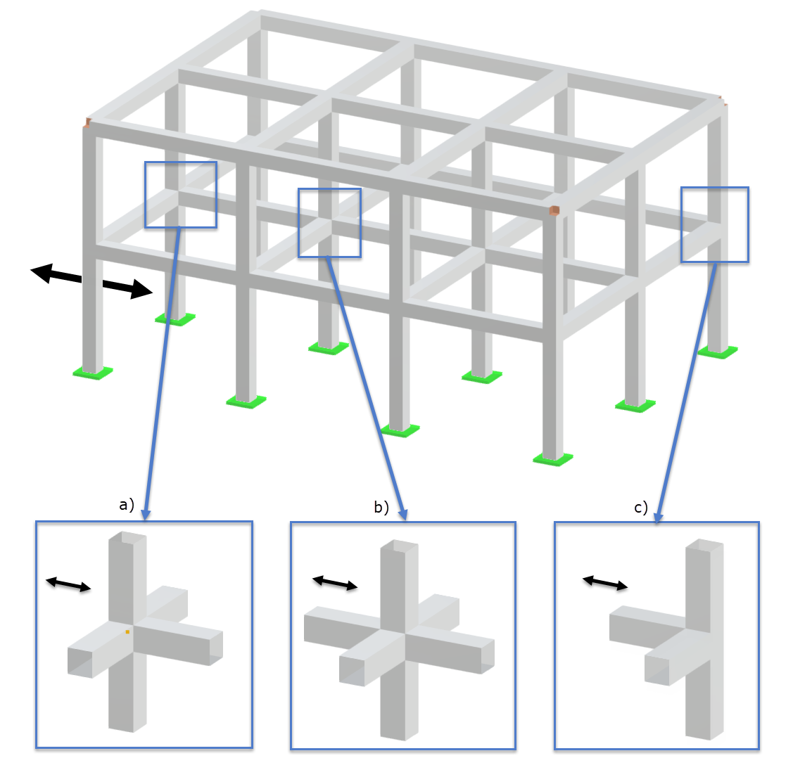
Illustration a) in the following image shows the forces acting on an internal beam-column connection node due to seismic loading.

Illustrations b) and c) show the mechanism of shear load transfer for the node area. This can be divided into two components.
In the first mechanism b), the compression strut mechanism, the joint shear force is concentrated on a compressed diagonal concrete compression strut. The transverse reinforcement provides a restraint for the concrete, which allows for greater deformability of the strut, but only up to the yield stress of the steel.
In the second mechanism c), the truss mechanism, the part of the shear force, which is related to the
bond stress along the longitudinal reinforcement within the node area, is in equilibrium with a truss mechanism given by concrete compression struts and vertical and horizontal stirrup reinforcement of the node area.
The shear capacity is the sum of the shear force components with respect to these two mechanisms.
Inner and Outer Beam-Column Connection Nodes
Since the seismic behavior of the beam-column connections is governed by their position in the spatial (three-dimensional) reinforced concrete frame, it is necessary to distinguish between inner and outer nodes.
The following image illustrates the seismic node types.
Determination of Horizontal Shear Force Vjdh on Concrete Core of Node
Determination Required for DCH
Within the beam-column connection, there is a jump in the moment distribution of the columns. The concrete core of the connection is therefore exposed to very high shear stresses. This behavior is shown in the following image.
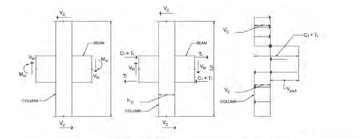
To determine the horizontal shear force acting on the connection core between the primary beams and columns, it is necessary to apply the most unfavorable conditions due to seismic action. This means, for example, that the capacities of the beams in the connection with the lowest shear force values are combined with the other frame elements.
The acting horizontal shear force Vjdh can be determined accordingly according to EC8, 5.5.2.3 (1) to (3) using the following calculation formulas.
- For inner nodes according to (5.22)
|
As1 |
Surface of the longitudinal reinforcement of Beam 1 |
|
As2 |
Surface of the longitudinal reinforcement of Beam 2 |
|
VC |
Shear force of thé column above the node j in the seismic design situation |
|
yRd |
Factor to consider overstrength; should not be less than 1.2 |
- For outer nodes according to (5.23)
|
As1 |
Surface of the beam longitudinal reinforcement |
|
VC |
Shear force of the column above the node j in the seismic design situation |
|
yRd |
Factor to consider overstrength; should not be less than 1.2 |
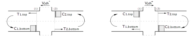
When determining the horizontal shear force Vjdh, it is necessary to check all governing directions. This means that for the shear force in the y-direction of the column, for example, both the positive and negative horizontal shear forces are determined using the corresponding reinforcement components. The force equilibrium of the positive and negative directions of the horizontal node shear force is shown in the following image (where the column shear force is not displayed).
Design
Design verification is required according to EC 8 for ductility class DCH. This requires design of the cross-section for the transfer of diagonal pressure and diagonal tension.
Structural rules for both the high ductility class (DCH) and the medium ductility class (DCM) must be complied with.
Design of Diagonal Compression
Design Required for DCH
It has to be ensured that the diagonal pressure generated in the node does not exceed the compressive strength of the concrete when transversal tension stress is present. The diagonal pressure results from the diagonal strut mechanism of the node.
The design can be carried out using the equations summarized below. (EN 1998-1, 2013, Section 5.5.3.3, (5.33))
|
bj |
Effective support width |
|
Vjdh |
Horizontal shear force acting on the concrete core of nodes |
|
|
Reduction factor due to tensile strains in the transverse direction |
|
|
Related value of the axial force in a seismic design situation |
|
hjc |
Distance between thé outermost layers of the column reinforcement |
Effective Node Width bj
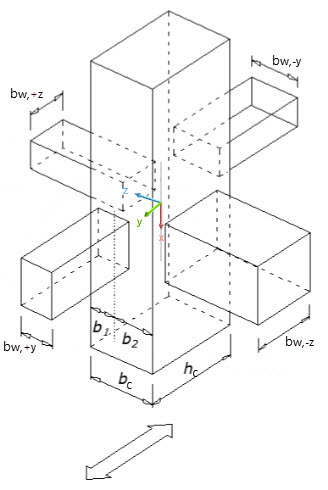
The effective node width bj can be calculated using the equation described below. (EN 1998-1, 2013, Section 5.5.3.3, (5.34a) and (5.34b))
This requires the determination of the contributing node widths in both directions (y and z) of the column, checking both beams (+y and -y and +z and -z) of the node, if necessary.
Design of Diagonal Tension
Design Required for DCH
Construction Rules
To be considered for DCM and DCH
Horizontal Confining Reinforcement
The horizontal confining reinforcement in the nodes of primary beams and columns subjected to seismic loads should not be smaller than the stirrup reinforcement in the critical areas of the columns, that is, the stirrups must pass through the node.
Longitudinal Reinforcement
It is necessary to provide at least one vertical intermediate member on each side.