


With the reinforcement set type Member | Cross-section, you define the reinforcement of members and member sets. The longitudinal reinforcement is defined by the number and diameter of the rebars, and the shear reinforcement by the stirrup type, stirrup diameter, and stirrup spacing. The inputs are distributed across the Reinforcement Bars and Shear Reinforcement tabs.
In the Assigned to Members No. / Member Sets No. box, you specify the members or member sets to which the reinforcement set applies. The automatically generated Name contains, in addition to the reinforcement set type, the selected reinforcement layout, for example 'Member | Cross-section | Top Side (-z) and Bottom Side (+z) | 2'.

"Reinforcement Bars" Tab
In the Reinforcement Bars tab, you define the material, layout, and basic reinforcement of the longitudinal reinforcement. Additionally, you activate the options for further reinforcement here.
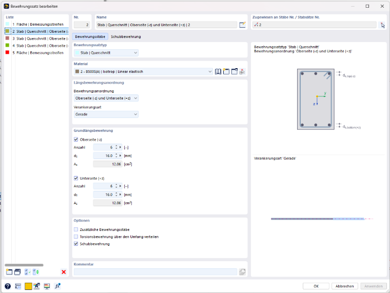
Reinforcement Set Type

In the list, select the type Member | Cross-section.
Longitudinal Reinforcement Layout
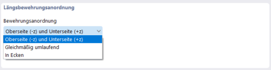
The reinforcement layout defines how the longitudinal reinforcement is distributed in the cross-section:
- Top Side (-z) and Bottom Side (+z): The reinforcement is arranged separately on the top and bottom sides of the cross-section.
- Evenly Around Perimeter: The reinforcement is evenly distributed over the perimeter of the cross-section.
- In Corners: The reinforcement is arranged in the corners of the cross-section.
The input boxes in the Basic Longitudinal Reinforcement section adapt to the selected reinforcement layout.
The anchorage type defines how the reinforcement bars are formed at their ends.
Basic Longitudinal Reinforcement
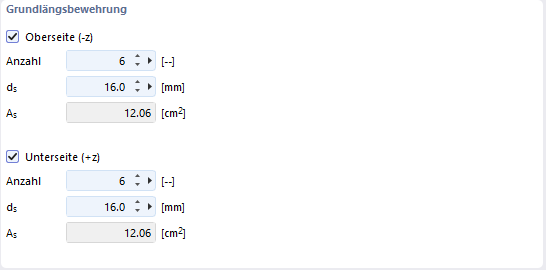
For the reinforcement layout 'Top Side (-z) and Bottom Side (+z)', activate the check boxes of the sides on which basic reinforcement is present:
- Top Side (-z): side in the direction of the negative local z-axis
- Bottom Side (+z): side in the direction of the positive local z-axis
For each activated side, enter the number of reinforcement bars and the rebar diameter ds. The program determines the reinforcement area As from these:
\[ A_s = n \cdot \frac{\pi \cdot d_s^2}{4} \]
For example, for 6 bars Ø16, As = 12.06 cm². If a check box is deactivated, the input boxes of the respective side are locked.
Options

In the Options section, you define which reinforcement is taken into account in addition to the basic longitudinal reinforcement:
- Additional Reinforcement Bars: In addition to the basic longitudinal reinforcement, further reinforcement bars can be defined.
- Distribute Torsional Reinforcement Around Perimeter: The longitudinal reinforcement for torsion is distributed over the perimeter of the cross-section.
- Shear Reinforcement: If the check box is activated, the Shear Reinforcement tab appears next to the Reinforcement Bars tab.
"Shear Reinforcement" Tab
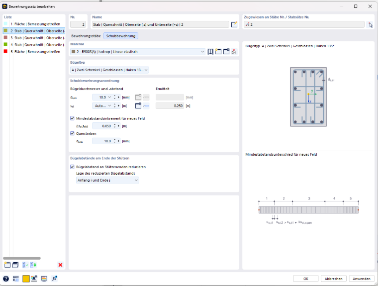
In the Shear Reinforcement tab, you define the material, stirrup type, and layout of the stirrups.
Stirrup Type
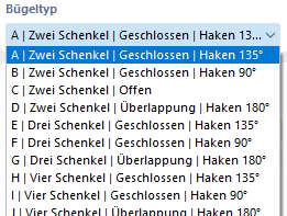
In the list, select the stirrup shape. The name of each type indicates the number of legs, the design of the stirrup (closed, open, or with overlapping), and the hook shape, for example 'A | Two Legs | Closed | Hook 135°'. Stirrups with two, three, or four legs are available for selection.
Shear Reinforcement Layout
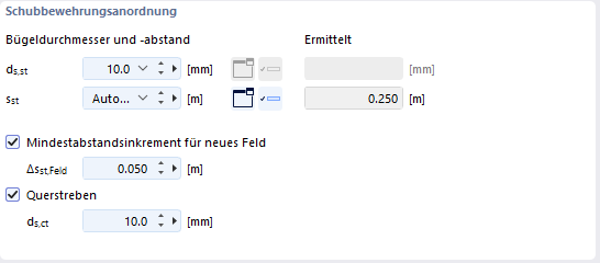
Under Stirrup Diameter and Spacing, you define the stirrup diameter ds,st and the stirrup spacing sst. You can select both values from the list or enter them directly. With the 'Automatic' setting, the program determines the value itself during the design. The Determined column shows the value determined by the program, for example sst = 0.250 m. These fields cannot be edited.
Using the button to the right of the input box for ds,st, you open the Additional Parameters dialog box with the list of possible stirrup diameters. The list is preset with the standard diameters for stirrup reinforcement defined in the Global Settings. If you enter other diameters in the dialog box, the values from the dialog box apply to this reinforcement set.
Using the Minimum Spacing Increment for New Field check box, you control when a new stirrup field with a different spacing begins along the member. A new field is only created if its stirrup spacing differs from the spacing of the adjacent field by at least Δsst,field. This avoids many short fields with nearly identical stirrup spacing.
Using the Cross-Ties check box, you arrange additional cross-ties with the diameter ds,ct.
Stirrup Spacings at Column Ends
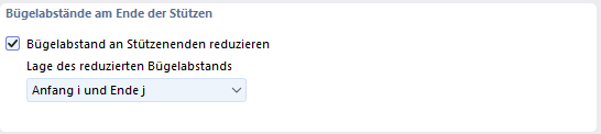
The Reduce Stirrup Spacing at Column Ends check box reduces the stirrup spacing at the ends of columns. Under Position of Reduced Stirrup Spacing, you select at which member ends this applies, for example 'Start i and End j'.