


By applying constriction to the concrete cross-section with shear reinforcement, the lateral strain of the concrete is limited, thereby increasing its compressive strength and ductility. The effect is displayed schematically in the following image from [2].
![Circular and rectangular compression elements with confining reinforcement (source: [2])](/en/webimage/061793/5174079/2026-03-12_umschnürter_Beton-0.75.png?mw=760&hash=9bad273554eba0badbdaa8ca78aac65cba97af65)
These effects are important for the seismic design of columns, as they ensure the availability of plastic deformation capacity and can improve the global load-bearing capacity of the structure in the event of an earthquake.
Design Model According to Eurocode 2
DIN EN 1992-1-1 does not provide an explicit design approach for constricted compression elements.
However, according to Section 3.1.9 of DIN EN 1992-1-1 [1], a multiaxial stress state may be taken into account in the design by applying a modified effective stress-strain relation with increased strengths and limit strains. It should be noted that these increased strength and strain values apply exclusively to the constricted concrete core, which is limited by the center lines of the confining reinforcement.
The load-bearing contribution of the concrete cover is generally not to be considered in the ULS, since the concrete cover is usually no longer effective due to spalling.
Unless more precise data is available, a parabolic-rectangular diagram according to [1], Figure 3.6, may be used for the constricted core concrete. It is necessary to use accordingly adjusted characteristic strength and strain values as a basis.
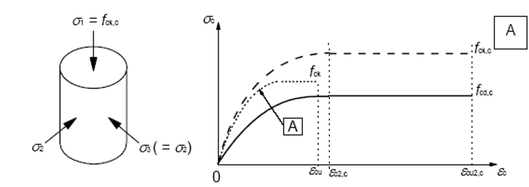
The strength of the constricted concrete core is described by the following formula.
|
|
Efficient transverse compression stress in the ULS due to transverse strain restriction |
The characteristic strains are determined using the following formulas.
|
|
Concrete elongation upon reaching fck according to EC2, Table 3.1 |
|
|
Concrete ultimate strain under uniaxial compressive stress EC2, Table 3.1 |
Eurocode 2 does not provide any guidelines for determining the transversal compression. Therefore, DAfStb Heft 630 ([2], 3.5.4) refers to the approaches of Mander et al. The equations for determining the transverse compression are described in the following section. σ2 = σ'l
Analysis Model According to Mander et al.
The model developed by Mander et al. explicitly describes the stress-strain behavior of constricted concrete as a function of the effective confining pressure. From this, an increased effective compressive strength and an increased peak strain of the constricted concrete core are derived, as well as a ductile, gradually decreasing stress-strain curve. Among others, the input parameters include the reinforcement content and arrangement of the stirrups/spirals, their steel strength, and the geometry of the enclosed core cross-section.
![Comparison of the stress-strain relation of concrete and constricted concrete according to Mander [3], displayed in blue and red.](/en/webimage/061798/5174060/2026-03-12_Confined-Concrete-Mander.png?mw=760&hash=b32998402db5d7db3d107eb9e43d82e1dfce9813)
The stress-strain relation is described by the following equation, [3] (3), (4), (6), (7), and (8).
The corresponding strain can be described by the following formula, [3] (5).
The compressive strength of the constricted concrete is given according to [3] (29).
The effective transverse compression stress for this can be determined from the equation below.
|
ke |
Effective Constriction Coefficient |
|
|
Volume ratio between confining reinforcement and confined core concrete |
|
fyw |
Yield stress of the transverse reinforcement |
The effectivity coefficient of the constriction is given according to the following expression.
Where the net core concrete surface can be determined from:
|
|
=Asl/Acc longitudinal reinforcement ratio of the constricted concrete core |
The effective constricted concrete surface can be determined from
|
dc |
Diameter of the constricted core concrete |
|
ac, bc |
Horizontal dimensions of the constricted core concrete |
|
s' |
Light spacing of the confining reinforcement in the direction of the compressive stress |
|
w'i |
Clear distance between the longitudinal rebars |
Application
The design model according to EC2, 3.1.9 is used for standard-compliant ultimate limit state design checks that allow for an increase in compressive strength due to constriction.
The Mander model (Mander et al., 1988) is used as a physically based material model when the full σ < sub > c < /sub > - εc behavior of constricted core concrete (increased fcc, εcc, post-peak behavior) needs to be taken into account for nonlinear analyses.