


Connectors are used to connect the individual parts of a composite cross-section to each other.
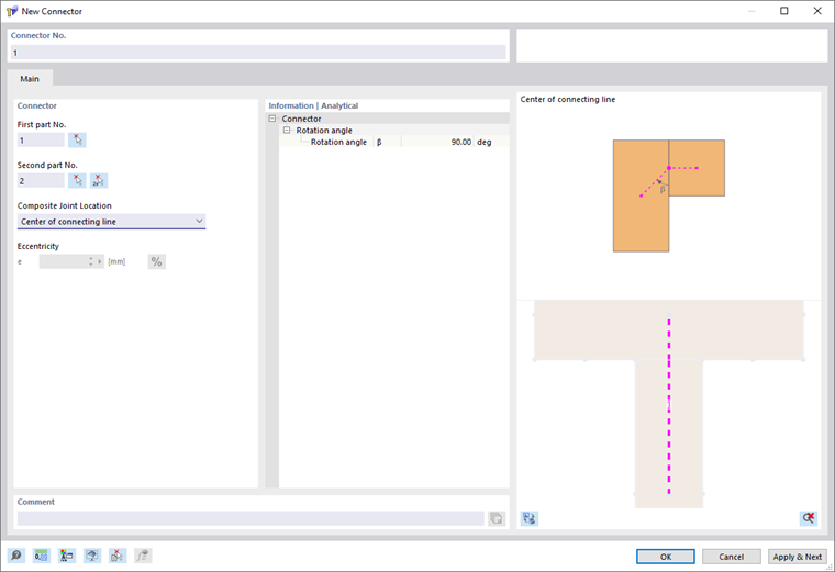
The connector number is assigned automatically, but can be changed. The order is irrelevant for the numbering. It does not have to be consecutive, either; gaps in the numbering are allowed.
First Part No. / Second Part No.
With the first and second part, you define which parts are connected to each other by the connector. The assignment as the first or second part is relevant for later use in RFEM. If a line hinge is defined for the connector in RFEM, it is positioned on the first part.
Position of Composite Joint
The connector is generated between the centers of gravity of the two parts. The composite joint lies on the common connection line of the two parts. Thus, the connector runs from the center of gravity of the first part to the composite joint and from there on to the center of gravity of the second part.
With the Middle of Connection Line selection, the composite joint is arranged in the middle of the common connection line. Alternatively, you can use the Middle of Connection Line with Eccentricity selection to define an eccentric position of the composite joint on this connection line. The eccentricity is defined in the Eccentricity e field.
If the two parts do not have a common connection line, the connector is defined directly between the centers of gravity of the two parts. In this case, no position of the composite joint on a connection line can be defined.
Information | Analytical
This section shows the angle between the connector of the first part and the common connection line of the two parts.