


For the design with 'Finite element analysis', the results are displayed on the parts.
Displaying result values
You can control in the 'Navigator - Results' whether result values are displayed on the parts and which results are shown in detail. To do this, use the entries Values on Parts in the two navigator sections.
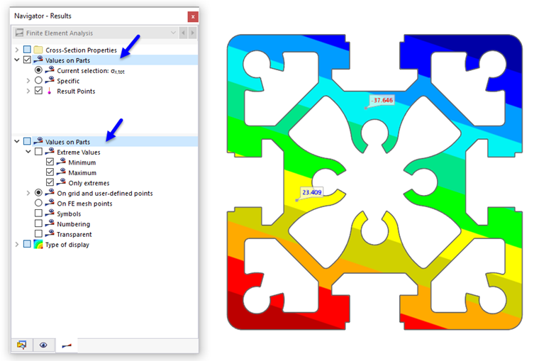
With the 'Values on Parts' category in the upper section, you can switch the display of the result values on and off. Here, you also specify the result type(s) whose values are to be displayed.
The 'Values on Parts' category in the lower section manages several settings that you can use to influence the output and display of the result values.
Result category for values
In the upper navigator section, you specify the result category to be used for the value display.
Current Selection
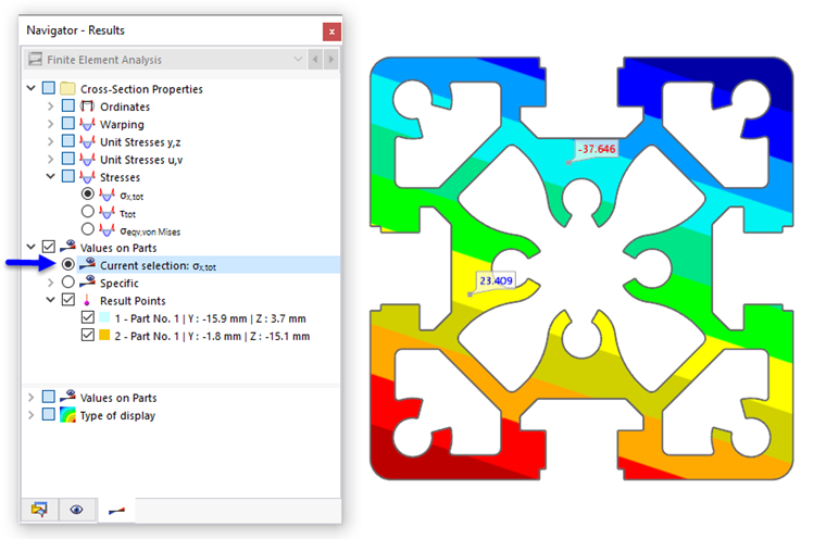
The 'Current Selection' option is aligned with the graphical results: In the image above, these are the axial stresses σx,tot. In this way, the result values of the current ordinate or stress graphic are displayed.
Specific
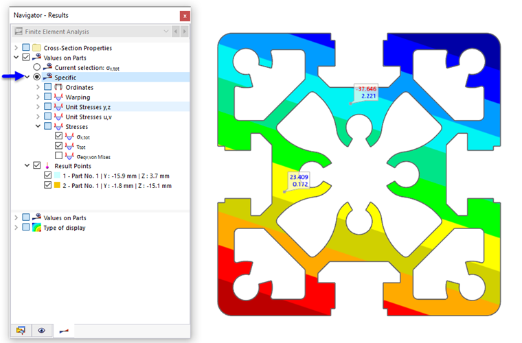
With the options of the 'Specific' selection field, you can individually specify which result values are displayed: ordinates, warping, unit stresses, stresses. The image above shows the values of the axial and shear stresses.
Settings for result values
In the lower navigator section, you can specify at which points result values are displayed and in which form they appear.
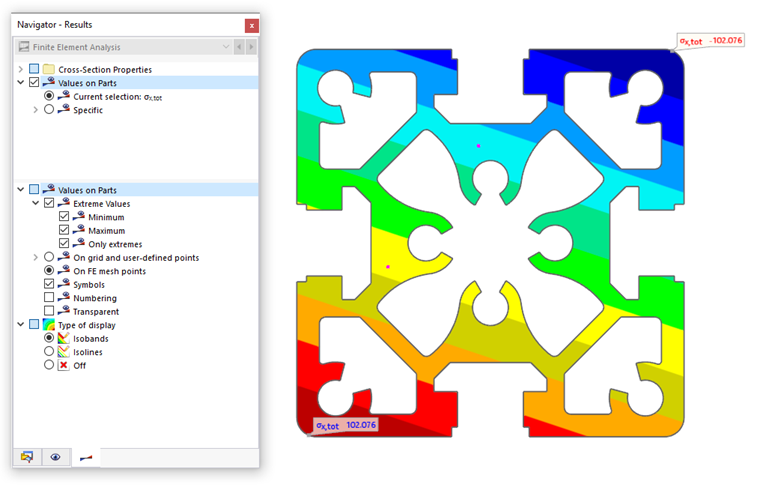
Extreme Values
With the 'Extreme Values' check box, you can control whether only the extreme values of the results are displayed. Depending on the setting, the respective minima or maxima of the parts appear. The image above shows the minimum and maximum axial stresses σx,tot that exist in the entire cross-section.
At Grid and User-Defined Points / At FE Mesh Points
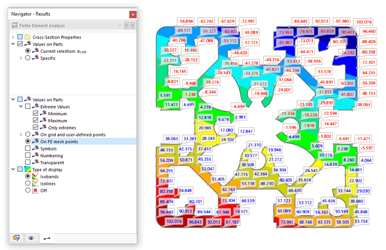
The result values are displayed either at the grid points (in preparation) and user-defined result points or at the FE mesh points. The image above shows the maximum axial stresses σx,tot that exist at the nodes of the mesh.
The settings for the result grid of a part can be made in the dialog box
Edit Part
(in preparation). The user-defined result points, in turn, are managed in the result objects. With the button
 , you can also set result points directly.
Symbols / Numbering / Transparent
The last three check boxes of the lower section 'Values on Parts' control how the values are displayed.
- Symbols: The result type (u, ωSC, σx,tot) is also specified.
- Numbering: The number of the grid point R, FE mesh point N, or result point U is displayed.
- Transparent: The values are displayed without a frame and without a background.
Display type
The results can be displayed as isosurfaces or isolines, with the color assignment according to the scale in the control panel. With the 'Off' display type, an output of the pure result values is possible: The isosurfaces or isolines are hidden so that only the result values at the grid or FE mesh points are displayed.
Adjusting color and font of result values
To adjust the colors and font of the result values, select the Display Properties function in the Options menu. In the 'Display Properties' dialog box, open the Results category. Select the Values on Parts entry.
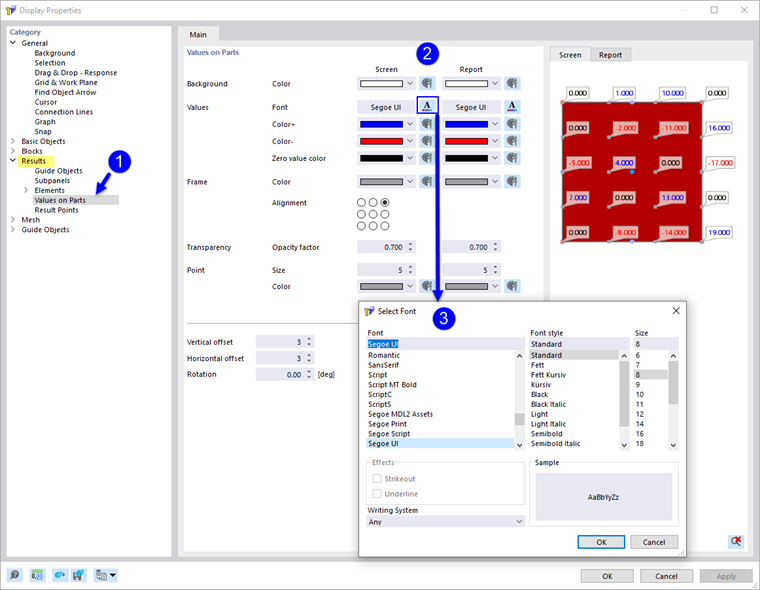
In the 'Values on Parts' section, you can now adjust the color of the background and the frame, the font, the arrangement, and the transparency. The changes are displayed in the preview on the right.
Separate presets are possible for the 'Screen' and the 'Printout Report'. If the button
 is activated, the changes are synchronized for both output types.