


Die im Add-on Stahlanschlüsse analysierten Verbindungen verwenden ein Ersatz-Stahlanschluss-FE-Modell („Submodell”) für die Bemessung. Dieses Modell wird anhand der Topologie des Anschlusses erstellt. Einzelne Bemessungskomponenten wie Bleche, Schweißnähte oder Schrauben werden in diesem Modell durch grundlegende FE-Objekte – Flächen oder Stäbe – dargestellt, die durch spezielle Objekte wie Flächenkontakte oder starre Kopplungen ergänzt werden. Dieser Ansatz ermöglicht es, das Verhalten der Grundkomponenten mit den analytischen Formeln der Bemessungsnormen zu vergleichen. Mit Hilfe dieses „Submodells” können die Tragfähigkeit und Beulfestigkeit sowie die Steifigkeit und Verformungskapazität der Verbindung analysiert werden.
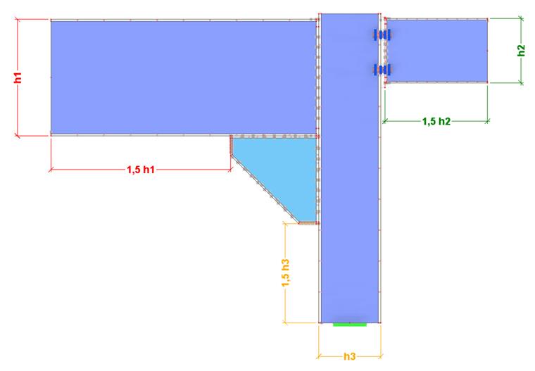
Die Dimensionen des Submodells werden proportional zur Querschnittsgröße der angeschlossenen Stäbe bestimmt. Mit 2D-Flächen modellierte Stäbe werden axial um ein Vielfaches der größten Querschnittsabmessung über die Anschlusskomponenten hinaus verlängert. Dieser Faktor entspricht standardmäßig 1,5, kann aber in der Tragfähigkeitskonfiguration angepasst werden. Als Referenz für den Abstand dient die am weitesten entfernte Komponente des Anschlusses.
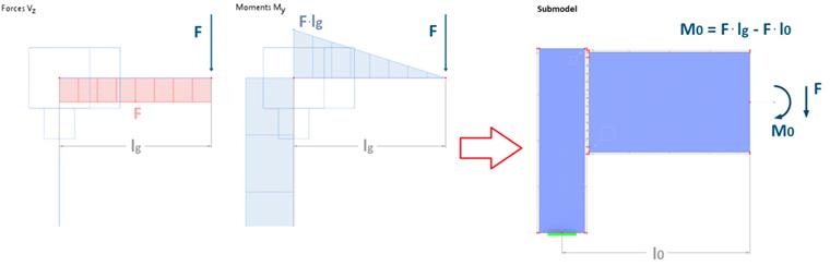
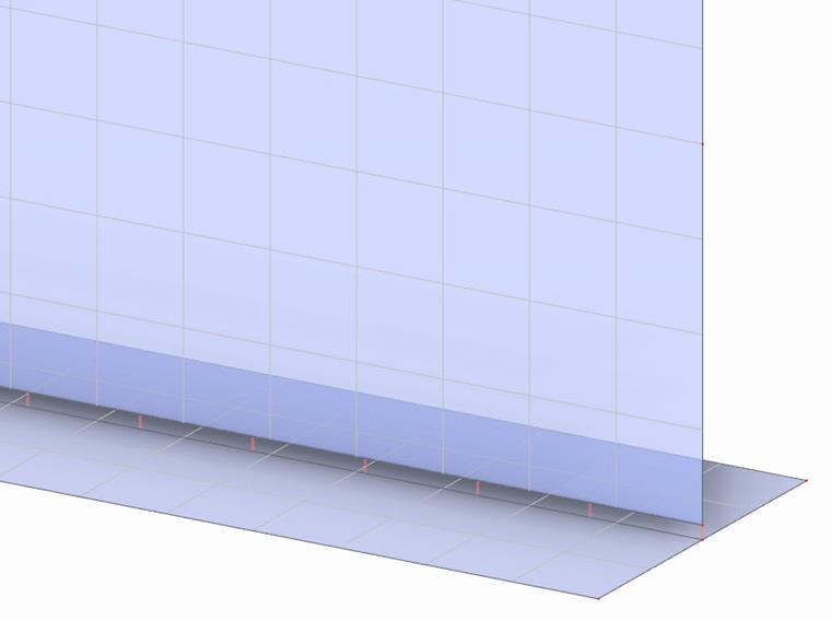
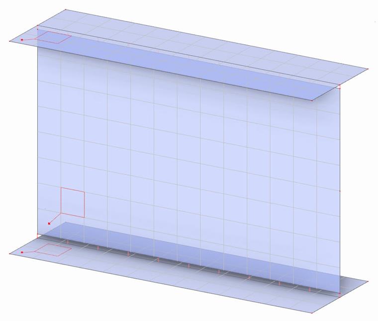
Im Submodell wird das Ende eines angeschlossenen Stabs je nach Benutzereinstellungen entweder starr gelagert, oder durch eine im globalen Modell berechnete Ersatzlast belastet. Die Lasten an den Enden der Stäbe basieren auf den Schnittlasten aus dem Gesamtmodell unter Berücksichtigung der jeweiligen Einstellungen für die statische Analyse und werden so angepasst, dass ihre Wirkung den Schnittlasten auf das betreffende Bauteil in dem Knoten entspricht, dem der Anschluss zugeordnet ist. Die Enden des Stabes werden mit einer Starrfläche versteift, um ein Verziehen des Querschnitts zu verhindern und Spannungskonzentrationen im belasteten oder gelagerten Knoten zu vermeiden.
Standardmäßig verwendet das Ersatz-Stahlanschluss-FE-Modell geometrisch lineare Analyse in Verbindung mit einem nichtlinearen Materialmodell zur Berechnung der Tragfähigkeit. Zur Analyse der Nichtlinearitäten des Modells wird die iterative Newton-Raphson-Methode angewendet. Die nichtlineare Analyse zweiter Ordnung (P-Δ) wird als Standardeinstellung für die Strukturanalyse bei der Knickbewertung verwendet, während für die Stabilitätsanalyse die lineare Eigenwertmethode verwendet wird. Weitere Informationen finden Sie im Kapitel Einstellungen für die statische Analyse des RFEM-Handbuchs.
Wenn in der statischen Analyse des Hauptmodells die Theorie zweiter oder dritter Ordnung berücksichtigt wird, kann dies zu Inkonsistenzen zwischen dem Hauptmodell (Gleichgewicht wird auf dem verformten System hergestellt) und dem Submodell (Kräfte werden auf das unverformte Submodell ausgeübt) führen. Bei typischen Tragwerkssystemen sollte dieser Effekt jedoch vernachlässigbar sein.
Materialmodell
Flächen, die Stabplatten und eingefügte Bleche im Submodell darstellen, haben eine gleichmäßige Dicke und unterliegen einem isotrop-plastischen Materialmodell. Die Spannungsversagenshypothese basiert auf dem von-Mises-Fließkriterium. Es wird ein bilineares Diagramm verwendet, nach dem sich das Material bis zur Streckgrenze elastisch unter dem Elastizitätsmodul von Stahl verformt. In der anschließenden plastischen Phase entspricht der plastische Modul 1/1000 des Elastizitätsmoduls.

Das Kriterium zur Bestimmung der Grenzfestigkeit entspricht einer 5 %igen von-Mises-äquivalenten plastischen Dehnung. Dieser Wert wird empfohlen, kann aber in der Tragfähigkeitskonfiguration angepasst werden. Dies ermöglicht es, das plastische Verhalten von Stahl und die Spannungsumverteilungen in der Verbindung zu nutzen. Das entspricht dem realen Verhalten einer Stahlverbindung in guter Näherung.
Stäbe und Bleche
Für die Modellierung von ebenen Stabplatten und eingefügten Platten werden der Geometrietyp Ebene und der Steifigkeitstyp Standard verwendet. Die Flächen haben eine gleichmäßige Dicke und sind mit einem isotrop-plastischen Materialmodell versehen, das im Abschnitt Materialmodell beschrieben ist. Die Flächen sind 2D-Objekte, die in den Mittelebenen der Bleche liegen. Wenn die einzelnen Bleche, die den Stab darstellen, nicht direkt über ihre Begrenzungslinien verbunden werden können, wird eine Verbindung mit starren Kopplungen hergestellt. Der Kopplungstyp „Linie zu Linie“ verbindet die Begrenzungslinie des verbundenen Blechs mit der integrierten Linie, die in dem Blech erstellt wird, mit dem es verbunden ist. Diese Verbindung wird beispielsweise für I-Profile verwendet.
Stäbe oder Teile davon aus nicht ebenen Flächen, wie z. B. kreisförmige Hohlprofile oder abgerundete rechteckige Hohlprofile, werden durch Segmentierung des gekrümmten Abschnitts als kleinere ebene Flächen modelliert. Diese Flächen haben die gleichen Eigenschaften wie Flächen, die für ebene Bleche verwendet werden. Der Grad der Segmentierung kann vom Benutzer in der Tragfähigkeitskonfiguration angepasst werden.
Netz
Die Netzeinstellungen für alle Flächen ermöglichen dreieckige und viereckige finite Elemente mit der Option „Gleiche Quadrate generieren, wo möglich“.
Die Bleche jedes Stabs haben die gleiche Netzelementgröße. Die minimalen und maximalen Elementgrößen sind standardmäßig festgelegt. Die Größe eines Elements wird aus der Querschnittsgröße des Stabs abgeleitet. Standardmäßig wird die längste Kante des Querschnitts in acht Teile unterteilt. Die Netz-Einstellung eingefügter Bleche wird separat behandelt: Die Größe des Netzelements wird aus der längsten Kante des Blechs abgeleitet. Für ein Blech ohne Schrauben werden standardmäßig acht Elemente auf der längeren Kante erstellt, für ein verschraubtes Blech sind es standardmäßig 16 Elemente.
Im Bereich von Schrauben wird eine kreisförmige Knotenvernetzung auf die Flächen der verschraubten Bleche angewendet. Für diese kreisförmige Knotenvernetzung ist es möglich, den Radius als Vielfaches des Schraubenlochradius festzulegen sowie die Anzahl der Elemente an der Lochkante festzulegen.
Für die Ersatzfläche der Kehlnaht können die maximale Anzahl von Elementen entlang der Länge der Schweißnaht sowie die minimale und maximale Größe der Elemente festgelegt werden.
Netzknoten werden über Starre Kopplungen und Flächenkontakte mit verbundenen Linien oder Flächen verbunden. Dies hat Auswirkungen auf das Netz der verbundenen Fläche, sodass deren Diskretisierung nicht vollständig unabhängig ist.
Schrauben
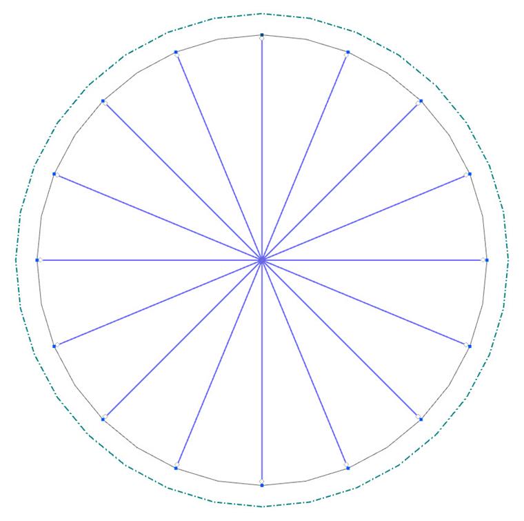
Das Schraubenmodell besteht aus einem System von Stäben, Flächen und Flächenkontakten, die die einzelnen Teile der Schraube, den Schaft, den Kopf und die Mutter, darstellen. Für jede Schrauben wird in den verschraubten Blechen automatisch eine Bohrung generiert.
Die Bohrung wird mit radial angeordneten Stäben gefüllt, die als „Speichen” bezeichnet werden. Diese Stäbe vom Typ „Balken” dienen zur Übertragung der Scherkraft zwischen dem Schraubenschaft und dem Blech. Die Anzahl dieser Stäbe wird durch die Netz-Einstellung beeinflusst und entspricht der Anzahl der Elemente am Lochrand. Der Querschnitt dieser Stäbe ist ein „massives Rechteck”, dessen Abmessungen von der Anzahl der Stäbe und den Abmessungen der verschraubten Bleche beeinflusst werden. Sie entsprechen der Fläche des Schraubenschaftes im Lager.
Ein Stabendgelenk wird den Knoten zugewiesen, an denen die Speichen mit dem Blech verbunden sind. Das Gelenk ist jeweils so eingestellt, dass die Stäbe das Loch im Blech nicht aussteifen und nur die Scherkraft zwischen dem Blech und der Schraube übertragen.
Die Speichenelemente weisen eine Nichtlinearität vom Typ „Ausfall bei Zug” auf, damit nur der komprimierte Teil der Schraube wirkt. Ihnen wird ein isotropes lineare-elastisches Material zugewiesen, das dem Stahl im elastischen Zustand entspricht.
Das Modell des Schraubenkopfes und der Mutter verwendet ebenfalls eine Reihe von radialen Stäben („Speichen”), da es sich auf das Loch des verschraubten Blechs bezieht. Diese Speichen unterscheiden sich jedoch in ihren Querschnittsabmessungen, sodass sie die Höhe des Schraubenkopfes beziehungsweise der Mutter darstellen. Darüber hinaus werden weder Gelenke an den Stabenden noch eine Ausfallnichtlinearität zugewiesen. Dieser Speichensatz wird durch eine ringförmige Fläche erweitert, die mit den radial angeordneten Speichen verbunden ist. Für die Fläche werden der Geometrietyp „Ebene” und der Steifigkeitstyp „Standard” verwendet, mit einer gleichmäßigen Dicke, die der Höhe des Bolzenkopfs oder der Mutter entspricht.
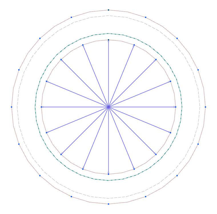
Die Mittelpunkte des radialen Systems von Stäben, die den Bolzenkopf, den Schraubenschaft im Loch und die Schraubenmutter darstellen, sind durch einen Stab verbunden, der den Schraubenkopf und das Gewinde darstellt. Ihm wird der Stabtyp „Balken” zugewiesen, und er wird als „Schaft” bezeichnet. Der Schaft hat einen kreisförmigen Querschnitt, dessen Fläche dem Spannungsquerschnitt der Schraube entspricht. Das Querschnittsmaterial ist isotrop linear elastisch.
Der Stab-Typ „Steifigkeit“ wird im Abschnitt zwischen den verschraubten Blechen verwendet. Die Steifigkeitsmatrix entspricht dem Stab, der zwischen dem Schraubenkopf (bzw. der Mutter) und dem verschraubten Blech verwendet wird; der einzige Unterschied besteht in der Biegesteifigkeit, die deutlich erhöht ist. Würde die Steifigkeit nicht angepasst, käme es zu einer physikalisch unrealistischen Biegung des Schraubens an der Stelle, an der die Kräfte tatsächlich ausschließlich durch Scherung übertragen werden. Das plastische Verhalten dieses Teils des Schraubenschafts wird durch ein Stabgelenk vom Nichtlinearitätstyp „Diagramm” an der Schnittstelle der verschraubten Bleche dargestellt.
Die Druckkräfte, die beim Kontakt der verschraubten Bleche und zwischen diesen Blechen und dem Schraubenkopf oder der Mutter entstehen, werden durch Flächenkontakte übertragen. Diese werden zwischen der Oberfläche des Schraubenkopfringes und der Fläche, die das erste verschraubte Blech darstellt, zwischen den einzelnen verschraubten Blechen, die sich berühren und zwischen der Oberfläche, die das letzte verschraubte Blech darstellt, und dem Mutterring festgelegt. Der Flächenkontakttyp wird in senkrechter Richtung zu den Flächen auf „Ausfall unter Zug” und bei Kontakt parallel zu den Flächen auf „Starre Reibung” festgelegt. Hier wird der Reibungskoeffizient auf einen Wert nahe Null gesetzt. Diese Kontakte ermöglichen die Erzeugung der richtigen Zugkraft am Schraubenschaft.
Die Bemessungszugkraft und die Bemessungsquerkraft als Ergebnis der internen Scherkräfte in y- und z-Richtung, die für die Bemessungsprüfungen verwendet werden, entstehen am Schaft zwischen den verschraubten Blechen.
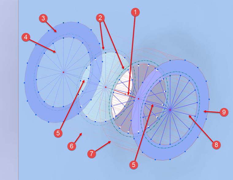
Die Zahlen in der obigen Abbildung bezeichnen die folgenden Komponenten:
| 1 | Schraubenschaft – Stab vom Typ „Steifigkeit" |
| 2 | Schraubenloch – Speichen |
| 3 | Mutter – Flächenring |
| 4 | Mutter – Speichen |
| 5 | Schraubenschaft |
| 6 | Mutter – Flächenkontakt |
| 7 | Schraubenkopf – Flächenkontakt |
| 8 | Schraubenkopf – Speichen |
| 9 | Schraubenkopf – Flächenring |
Vorgespannte Schrauben
Die Schraubenvorspannung wird wird im Rahmen eines eigenen Lastfalls im Submodell aufgebracht. Dieser Lastfall Schraubenvorspannung wird dann als Anfangszustand für den eigentlichen Bemessungslastfall berücksichtigt. Entsprechend des Vorspannkraftfaktors, der in der Tragfähigkeitskonfiguration vorgegeben wird (und standardmäßig nach EN 1993-1-8 bei 0,7 liegt), wird die Vorspannung in Abhängigkeit der Zugfestigkeit als Stablast auf den Schraubenschaft aufgebracht.
Schweißnähte
Das Modell der vollständig durchgeschweißten Stumpfschweißnähte verwendet eine direkte Verbindung zwischen den geschweißten Blechen. Es wird durch starre Kopplungen vom Typ „Linie zu Linie” umgesetzt. Die Verbindung ähnelt der Verbindung zwischen den Querschnittsteilen eines Stabes (Stabplatten). Dieser starre Kopplungstyp verwendet die Optionen „Benutzerdefinierte Verteilung” und „Einfluss des Abstands ignorieren”.
Das Modell der Kehlnähte verwendet ebenfalls ein System starrer Kopplungen (siehe ➁ in der folgenden Grafik) und Ersatzflächen (siehe ➀ in der folgenden Grafik) für die Schweißverbindung.
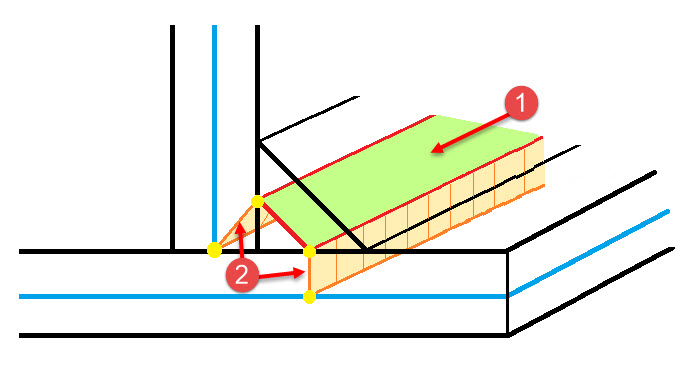
Der starre Kopplungstyp ist „Linie zu Linie“ mit den Optionen „Benutzerdefinierte Verteilung“ und „Einfluss des Abstands ignorieren“, wobei die Kante des angeschweißten Bleches mit der Kante der Ersatzschweißnahtfläche und die zweite Kante dieser mit dem Referenzblech verbunden wird. Die Ersatzfläche befindet sich auf halber Höhe des Dreiecksquerschnitts der Kehlnaht. Diese Höhe wird als „Halsdicke” der Kehlnaht bezeichnet. Die Ersatzfläche der Kehlnaht hat den Steifigkeitstyp „Standard” und eine gleichmäßige Dicke mit den Abmessungen, die der Halsdicke der Schweißnaht entsprechen. Es wird ein speziell and die Versagenskriterien gefittetes orthotrop-plastisches Materialmodell angewendet.
Das Schweißnaht-Materialmodell ist so eingestellt, dass es dem in den Normen berücksichtigten Schweißverhalten entspricht. Das bedeutet, dass nur Spannungen, die den Schweißspannungskomponenten σ⊥, τ⊥ und τ|| entsprechen, auf der Ersatzfläche auftreten. In den übrigen Spannungsrichtungen ist die Steifigkeit der Ersatzfläche nahe Null.

Beulanalyse
Der Ansatz des „Ersatz-Stahlanschluss-FE-Modells” eignet sich auch gut zur Bewertung des Beulens von Stahlblechen mithilfe einer FE-Analyse des Schalenmodells. Zu diesem Zweck wird das für die statische Analyse verwendete Modell in gewisser Weise angepasst, sodass schließlich das „Ersatz-Stahlanschluss-Beul-FE-Modell” („Beul-Submodell”) angewendet wird.
Die geänderten Einstellungen des „Beul-Submodells” lauten wie folgt:
- Alle verwendeten Materialien werden auf elastisch betrachtet (Stab- und Blechmaterial, alle Teile des Schraubenmodells, Schweißnahtersatzfläche).
Das Modell wird an den Enden durch aufgezwungene Knotenverformungen anstelle der Kräfte aus dem globalen Strukturmodell belastet. Diese Verformungen entsprechen Knotenlasten, ihre Verwendung stellt jedoch sicher, dass die freien Stäbe die Ergebnisse der Stabilitätsanalyse nicht negativ beeinflussen.
- Standardmäßig verwendet das Beul-Submodell den Analysetyp „Zweite Ordnung (P-Δ)“ für die statische Analyse und die „Eigenwertmethode (linear)“ mit den vier niedrigsten Eigenwerten für die Stabilitätsanalyse.
Nach der Berechnung liefert das Modell die erforderliche Anzahl von Eigenwerten mit dem jeweiligen kritischen Lastfaktor. Es obliegt dem Benutzer, zu beurteilen, ob die Stabilität des Stahlanschlusses ausreichend ist.
Steifigkeitsanalyse
Zur Bestimmung der Steifigkeit der Verbindung werden zwei Untermodelle verwendet. Dabei handelt es sich um das Hauptmodell Ersatz-Steifigkeits-FE-Modell (Steifigkeits-Submodell) – ein detailliertes Schalenmodell, das bis auf die Belastung und die Lagerung mit dem für die statische Analyse verwendeten Submodell identisch ist – und das Hilfs-Steifigkeits-FE-Modell (Hilfssteifigkeits-Submodell), das zur Berücksichtigung der Auswirkungen von Verformungen der verbundenen Stäbe verwendet wird.
Die Auslegungsparameter des „Steifigkeits-Submodells” werden in der Steifigkeitsanalyse-Konfiguration verwaltet. Mit dieser Einstellung können Sie den „Analysetyp” (geometrisch linear oder P-Δ zweiter Ordnung) auswählen sowie die „Maximale Anzahl von Iterationen” und die „Anzahl der Laststufen” definieren. Sie können auch die Modellgröße und die Netz-Einstellungen steuern, ähnlich wie bei den Einstellungen der Tragfähigkeitskonfiguration, die für die Spannungs-Dehnungs-Analyse der Verbindung gelten. Weitere Modellparameter werden ebenfalls aus der Tragfähigkeitskonfiguration übernommen.
Die Lastkomponenten, die auf beide Untermodelle (Steifigkeits-Submodell und Hilfssteifigkeits-Submodell) aufgebracht werden, entsprechen den zu untersuchenden Gelenksteifigkeiten. Die Steifigkeit wird für jeden Stab im Gelenk separat analysiert. Der analysierte Stab wird am Ende mit einer betragsmäßig geringen Last belastet, die der Art und Richtung der untersuchten Steifigkeit S (SN+, SN-, SMy+, SMy-, SMz+, SMz-) entspricht. Die anderen Stäbe in der Verbindung werden an ihren Enden starr gelagert. Die Lastgröße zur Bestimmung der „Anfangssteifigkeit” hängt von den Abmessungen jedes angeschlossenen Stabes ab.
Nach Durchführung der Berechnung wird das Steifigkeits-Submodell verwendet, um die Verformung (Drehung oder Verschiebung) am Ende jedes analysierten Stabes zu ermitteln. Die aus dem Hilfssteifigkeits-Submodell erhaltene Verformung wird von dieser Verformung subtrahiert, um die Steifigkeit der angeschlossenen Stäbe zu berücksichtigen. Das Ergebnis ist die aus der Last und der Verformung berechnete Steifigkeit der Verbindung. Basierend auf dieser Steifigkeit können die Verbindungen als „gelenkig”, „nachgiebig” oder „biegesteif” klassifiziert werden.