


In the navigator, define the deformations to be displayed on the surfaces. The table lists the deformations of each surface according to the specifications set in the Result Table Manager . There, you can also control which extreme values are displayed.
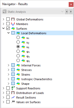
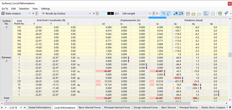
The Results by Surface in Table image shows the table with the global surface deformations. They refer to the X-, Y-, and Z-axes. The results shown in the Local Deformations of Surfaces in Table image refer to the surface axes x, y, and z.
The local displacements and rotations have the following meanings:
| |u| | Absolute value of the total displacement |
| ux | Displacement in the direction of the local x-axis |
| uy | Displacement in the direction of the local y-axis |
| uz | Displacement in the direction of the local z-axis |
| φx | Rotation about the local x-axis |
| φy | Rotation about the local y-axis |
| φz | Rotation about the local z-axis |
When analyzing curved surfaces, the surface axes refer to the axes of finite elements (see the image Displaying FE Axis Systems ).
Deformation State of Model
The list button in the toolbar allows you to display the shape of the real model in various deformation states.
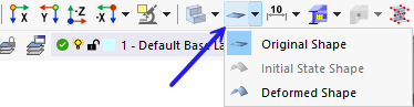
The functions of the buttons are described in the chapter Results by Node . Please note that the deformations are scaled by a fixed factor of 1.00.