In the Shape Orthotropy tab, you can describe the orthotropic properties by means of geometric parameters. The program determines the stiffness matrix elements based on these specifications.

Orthotropy Type
Various types are available for selection in the list (see the image above). Define the geometric shape that corresponds to the orthotropic properties of the thickness.
The "Parameters" section is adapted to the orthotropy type so that you can describe the geometry appropriately. The individual types are described below in the Parameters description.
Orthotropy Direction
The orthotropic properties refer to the xy-axis system of the respective surfaces (see the graphics in the dialog box). If the stiffnesses do not correspond to the orientations of the surface axis system, you can adjust the direction in this section.
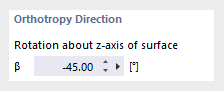
A positive angle β rotates the orthotropic stiffnesses clockwise about the positive z-axis of the surface. The matrices are transformed accordingly and displayed in the Transformed Stiffness Matrix tab.
Consideration of Self-Weight
When using shape orthotropies, there are usually different thicknesses for both directions. Specify the thickness that the program should apply when determining the self-weight. The list provides the following "Self-weight definition" options:
- Determined from parameters: The notional thickness is determined from the parameters of the x- and y-directions.
- User-defined fictitious thickness: Define the thickness dg manually.
- User-defined self-weight: Enter the self-weight wg as mass per unit of area.
Parameters
In this section, define the geometric properties of the orthotropy type.
Effective Thicknesses
You can define different thicknesses in the orthotropy directions x and y to represent unequal stiffness ratios (see the image New Thickness).
Coupling
With this orthotropy type, you can represent connections between surfaces or members that are available due to coupling elements.
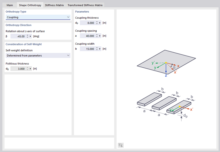
Enter the thickness of the coupling elements dp, the center distance a, and the width of the coupling elements b according to the scheme. A realistic coupling model is given when the distance of the coupled elements is larger than their width.
Unidirectional Ribbed Plate
The orthotropic properties of a ribbed floor are based on the principle of a uniaxially stressed T-beam slab.
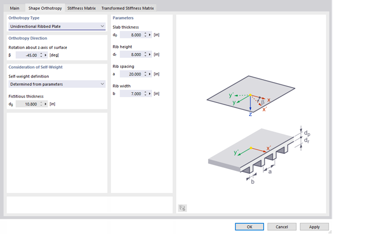
Enter the slab thickness dp, the rib height dr, the rib spacing a, and the rib width b according to the scheme. Based on these parameters, RFEM determines the stiffnesses for each direction.
Bidirectional Ribbed Plate
This type of ceiling is characterized by webs that cross each other orthogonally in a uniform grid, thus dividing the floor into coffers.
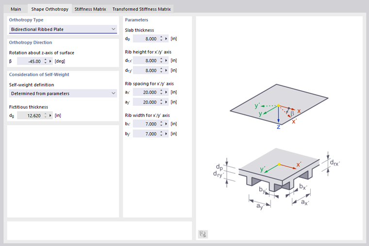
Enter the slab thickness dp and the rib height dr as well as the rib spacing a, and the rib width b according to the scheme.
Trapezoidal Sheet
You can display a trapezoidal sheet not only as a member, but as a surface with orthotropic properties.
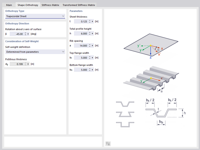
Enter the sheet thickness t, the total profile height h, and the center distance of the ribs a, as well as the top flange width bt and the bottom flange width bb according to the scheme.
Hollow Core Slab
Hollow units built in a ceiling reduce the self-weight, but produce orthotropic structural behavior.
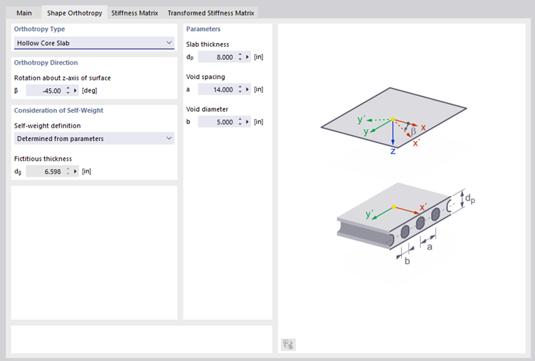
Enter the slab thickness dp, the void spacing a, and the void diameter b according to the scheme.
Grillage
You can display a grillage not only as a member model, but as a surface with orthotropic properties.
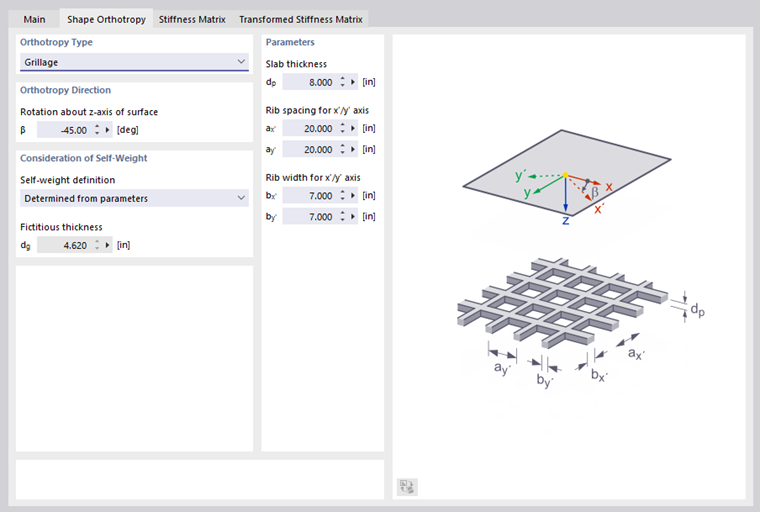
Enter the slab thickness dp, the center distances of the ribs a, and the rib widths b for both axes according to the scheme.
Stiffness Matrix
The Stiffness Matrix tab of the "New Thickness" dialog box shows the stiffness matrix elements (see the image Defining Stiffness Matrix ). The entries cannot be changed.
Transformed Stiffness Matrix
If the axes of the orthotropy are not consistent with the axes of the coordinate system of elements, you have to transform the matrices. The corresponding values are displayed in the Transformed Stiffness Matrix tab.
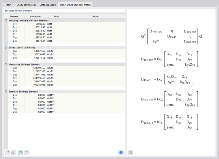
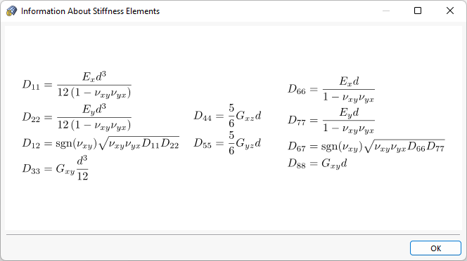
Use the
![]() button to open a dialog box with information for determining the matrix elements.
button to open a dialog box with information for determining the matrix elements.