The object snap facilitates modeling when placing lines, members, and surfaces. In addition to nodes, various snap points on objects can be used.
As a "Standard", nodes, centers, and line grid points are activated as snap points. For example, when placing a new line approaching an object with the pointer, the assigned symbols appear. They are described in the Table below.
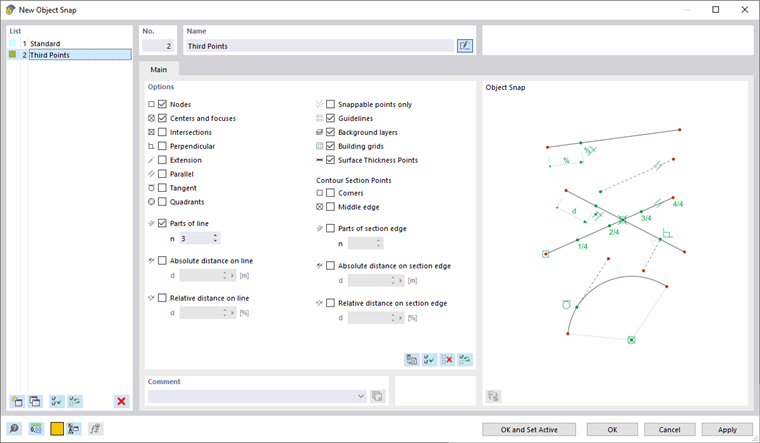
Use the check boxes in the "Options" dialog section to control the snap points to be active:
| Object | Snap Points |
|---|---|
| Nodes | Free nodes and nodes of lines |
| Centers and focuses | When moving the pointer near the center of a line, the focus of a curve, or the center of a surface or solid, it snaps into place. |
| Intersections | Intersection points of two lines that do not have a common node |
| Perpendicular | Perpendicular connection to a line |
| Extension | Connection to the straight line of a line that was preselected (briefly touched by the pointer) |
| Parallel | Placing a parallel line: After setting the start node, move the pointer over a pattern line. As soon as the pointer approaches a possible end node of the new line so that it is parallel to the pattern, the parallel symbol appears on the lines. |
| Tangent | Touch point of a line on the circular arc |
| Circle quadrants | Locations for the division of a circle in quarter points |
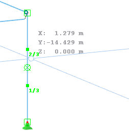
| Parts | Locations for the division of lines: When you move the pointer over a line, it snaps on the defined "n" divisions. On the cursor, the partition is displayed as a fraction. |
| Distance | Locations for the division of lines in absolute or relative distance: When you move the pointer over a line, it snaps on the defined "d" distances from the line start and line end. |
| Snappable points only | Placing nodes only on already defined objects, not in the work plane |
| Guidelines | Intersection of two guidelines |
| Background layers | Intersections of two lines of background layers |
| Building grid | Intersections of two lines of a building grid |
| Surface thickness points | Points for surface thicknesses near line definition nodes (not available for the wireframe model display) |
The options available for "Contour Section Points" provide snap options for locations on the rendered cross-section, such as corners, edges, or corner-related distances on the section edges. The snap points appear near the line definition nodes.

CAD Toolbar
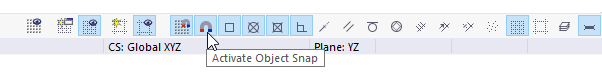
In the CAD toolbar below the tables, you can switch the object snap on and off, as well as individual snap functions.
The buttons have the following functions:
|
|
Turn the snap function on and off for grid points |
|
|
Turn the object snap on and off |
|
|
Snap on free nodes and nodes of lines |
|
|
Snap on centers and focuses |
|
|
Snap on intersections |
|
|
Snap on perpendicular points |
|
|
Snap on extensions |
|
|
Snap on parallel lines |
|
|
Snap on tangents |
|
|
Snap on quadrants |
|
|
Snap on division points of lines |
|
|
Snap on locations of lines with an absolute distance |
|
|
Snap on locations of lines with a relative distance |
|
|
Snap on snappable points only |
|
|
Snap on intersection points of a building grid |
|
|
Snap on intersection points of guidelines |
|
|
Snap on intersection points of background layers |
|
|
Snap on surface thickness points |