


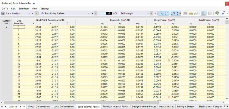
In the navigator, define the internal forces and moments to be displayed on the surfaces. The table lists the internal forces and moments of each surface according to the specifications set in the Result Table Manager .
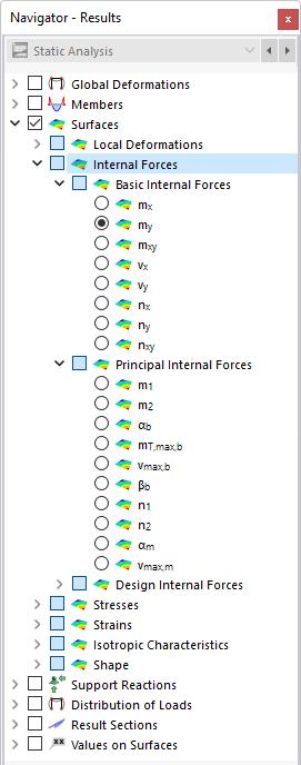
The surface internal forces are subdivided into three categories:
- Basic Internal Forces: internal forces and moments in the direction of the surface axes
- Principal Internal Forces: internal forces and moments in the direction of the principal axes
- Design Internal Forces: internal forces and moments according to DIN V ENV 1992-1-1 [1] Appendix 2, A 2.8 and A 2.9
Basic Internal Forces
In contrast to member internal forces, surface internal forces are symbolized by small letters. The integral definition of the bending moments mx and my shows that moments are related to the directions of the surface axes where the corresponding normal stresses are created.
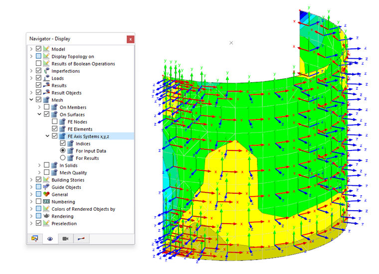
When curved surfaces are analyzed, internal forces and moments refer to the local axes of the finite elements. You can set the display of the "FE Axis Systems" in the navigator.
The following image shows the basic internal forces and stresses of a surface symbolically.
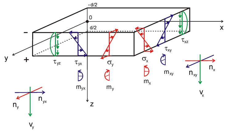
The surface moments as well as the shear stresses that are perpendicular to the surface show a parabolic distribution along the surface thickness.
Sign
The algebraic signs indicate the side of the surface on which the internal force or moment is available: If the global Z-axis is directed downwards, positive internal forces and moments generate tensile stresses on the positive side of the surface (that is, in the direction of the positive surface axis z). Negative internal forces and moments result in compressive stresses on the positive side of the surface. If the global Z-axis is aligned with upwards, the signs are reversed accordingly.
The basic internal forces and moments for a downward Z-axis are determined with the following equations.
Principal Internal Forces
While the basic internal forces and moments refer to the more or less freely created xyz-coordinate system of a surface, the principal internal forces and moments represent the extreme values of the internal forces and moments within a surface element. To determine the principal internal forces, the basic internal forces are transformed in the directions of both principal axes. The principal axes 1 (maximum value) and 2 (minimum value) are arranged orthogonally.
The principal internal forces and moments are determined from the basic internal forces and moments as follows:
You can graphically display the principal axes directions αb (for bending moments), βb (for shear forces), and αm (for axial forces) as trajectories.
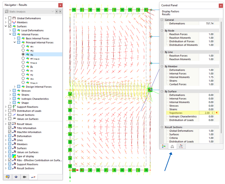
For example, if you display the angle αb, you can also see the magnitudes of the respective principal moments. The trajectories are scaled to the values of the moments m1 and m2.
Design Internal Forces
The design moments and axial forces are based on the approach described in DIN V ENV 1992‑1‑1 [1], Appendix 2, A 2.8 and A 2.9. This may help when performing reinforced concrete design checks manually. The design internal forces are irrelevant for the "Concrete Design" add-on, as the Baumann method [2] is used there.
The design internal forces are specified in Chapter 8.17 of the RFEM 5 manual.