


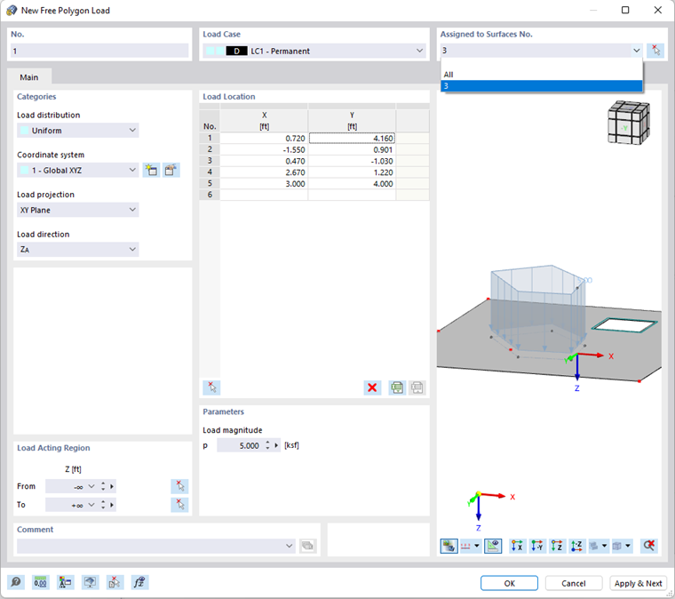
A free polygonal load acts as a uniform or linearly variable surface load on a polygon-shaped, freely definable zone of a surface.
In the list, select the "Load Case" to which you want to assign the load.
In the "Assigned to Surfaces" dialog section, you can control the effect of the polygon load. Several options are available for selection in the list (see the image New Free Polygon Load):
- "Empty": The load does not act on any surfaces.
- All: The load is applied to all surfaces that are cut perpendicular to the projection plane, starting from the load location.
- "Number": The load acts only on the surfaces of the specified numbers.
Categories
The following options are available for selection in the "Load distribution" list:
- Uniform: The polygon load acts with a constant magnitude.
- Linear: The load has a linearly variable magnitude.
- Linear in X / Y / Z: The load has a linearly variable magnitude in the direction of a global axis.
The load distribution scheme is illustrated in the upper dialog graphic.
If the polygonal area load does not refer to the global "Coordinate system" XYZ, you can select a user-defined coordinate system or create a new one.
In the "Load projection" list, select on which of the global planes (XY, YZ, or XZ) you want to project the load. Starting from the load location points, RFEM "designs" some straight lines perpendicular to this projection plane. The definition points of the polygon load result from the intersection points of these straight lines with the surfaces.
Select the "Load direction" from the list to define the effect of the load. Depending on the coordinate system, the local surface axes x, y, z, the global axes X, Y, Z, or the user-defined axes U, V, W are available for selection.

Load Location
You can enter the corner point coordinates of the load in the table or import them from an Excel spreadsheet with the
![]() button. Alternatively, you can define the polygonal chain graphically with the
button. Alternatively, you can define the polygonal chain graphically with the
![]() button.
button.
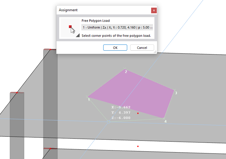
Once you have selected the last point, close the "Assignment" dialog box by clicking OK. You do not need to close the polygon.
Parameters
Specify the "Load magnitude" of the force.
For a linearly variable load, enter two load values; for a load that is linearly variable in X / Y / Z, enter three load values with the corresponding point numbers of the polygon load. You can define the points graphically with the
![]() button.
button.
Load Acting Region
As described above, the load acts on the surfaces that are cut perpendicular to the projection plane, starting from the load location. If you have selected the "All" option in the Assigned to Surfaces dialog section, you can limit the effect of the load by means of geometric criteria.
By default, the load acts indefinitely in the interval from -∞ to +∞. You can use the "From" and "To" text boxes to reduce the load effect to certain zones.