


Thicknesses are required for the definition of surfaces. The thickness properties are included in the stiffness of the surface. In the simplest case, you specify a uniform thickness of the surface. However, you can also use the thickness properties to describe orthotropic features or layer models.

Name
The name of the thickness is generated from the parameters that have to be defined for each thickness. You can replace this name with another name by clicking the
![]() button next to the text box.
button next to the text box.
Main
The Main tab manages the basic thickness parameters.
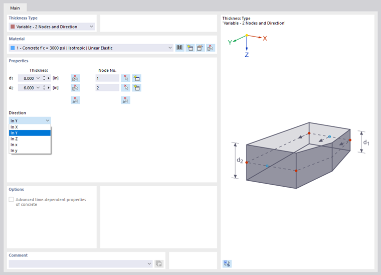
Thickness Type
The thickness type defines the geometry of the thickness. It affects the surface stiffness. Various thickness types are available for selection in the list.

Uniform
The standard type is suitable for surfaces that have a uniform thickness at any location. You can define the thickness in the "Properties" section.
Variable
A variable thickness describes a linear decrease or increase of the surface thickness. You can use different reference objects for the definition. Specify the thicknesses that are present at certain nodes. The variable thickness is then obtained by a linear interpolation.
You can use any nodes or create new ones to define the thicknesses. However, it is necessary that FE nodes can be generated on these locations.
Layers
The "Layers" thickness type is suitable for models whose surfaces have a multilayer structure. This thickness type is described in the chapter Layers.
Shape Orthotropy
The "Shape Orthotropy" thickness type allows you to define orthotropic object properties by using geometric parameters. The different types are described in the chapter Shape Orthotropy.
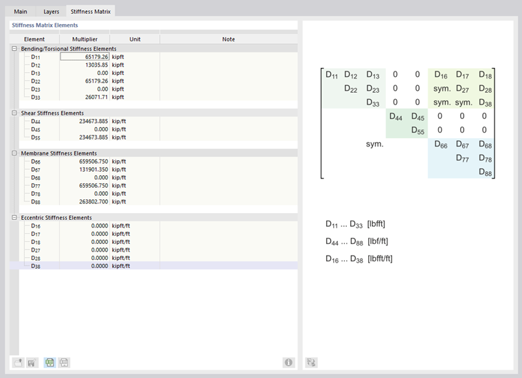
Stiffness Matrix
This type of thickness allows you to freely define the coefficients of the stiffness matrix. Define the orientation in the "Orthotropy" tab. Then, you can enter the matrix elements in the "Stiffness Matrix" tab.
Wall – Shear-Free
Using the "Wall – Shear-Free" thickness types, you can model the stiffness conditions of walls that only transfer axial forces, but no shear. This allows you to model masonry or timber stud walls, for example.

For shear-free thicknesses, for example, the shear stiffness element D44 is determined by dividing D44 of the regular thickness type by the larger value of D66 or D77. This low shear stiffness prevents the surface from becoming kinematic.
With the thickness types "Wall – Shear-Free in X" and "Wall – Shear-Free in Y", you can control whether only horizontal or vertical forces are transferred.
Beam Panel
In 3D models, you can use the "Beam Panel" thickness type to define load-bearing structures composed of members and surfaces, such as timber panel walls. This thickness type is described in the chapter Beam Panel.
Glass Composition
The "Glass Composition" thickness type is suitable for models with surfaces made of insulating or laminated glass. This thickness type is described in the chapter Layers.
Material
It is necessary to assign a material to all thicknesses with the exception of the Stiffness Matrix thickness type. You can select it from the list of already defined materials. The buttons next to the text box allow you to select a material from the library or to define a new one (see the chapter Materials).
Properties
Define the parameters in the "Properties" section for uniform and linearly variable thickness types. The parameters of a variable thickness are shown in the image Defining Variable Thickness.
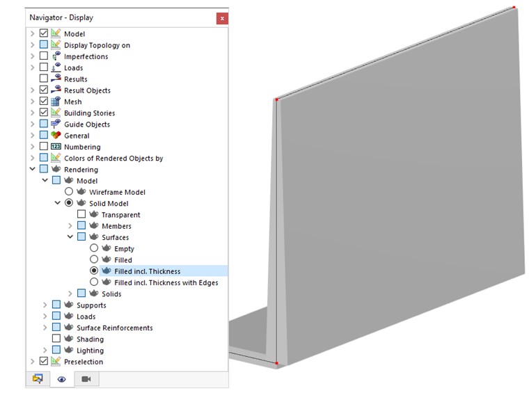
When you have assigned the thicknesses to particular surfaces, you can check the distribution of surface thicknesses in the rendering: Set the option Filled incl. Thickness in the "Navigator – Display".
Options
Cost Estimation
Cost estimation is typically based on the cost of the material assigned to the surfaces of a thickness (see the chapter Materials). If specific parameters are to apply to a thickness, you can define the unit costs and units separately in the Cost Estimation tab.
Estimation of CO₂ Emissions
The estimation of CO₂ emissions is also usually based on the material of the thickness. However, you can also specify the unit emissions and units specifically for each thickness in the CO₂ Emissions Estimation tab.
Cost Estimation
The Cost Estimation tab is displayed if you have checked the Cost Estimation option in the ‘‘Main’’ tab.
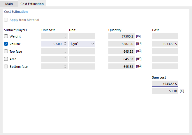
If cost estimation defaults already exist for a material of a certain thickness, the “Transfer from Material” check box is enabled by default. This applies the area-based unit cost definitions and prevents duplicate entries. If you want to define the unit costs and units separately for surfaces with a specific thickness, uncheck the box.
Select which thickness parameter is relevant for the cost estimation: weight, solid, top surface, area, or bottom side. Enter the value that one unit of the parameter costs in the “Unit Costs” column. The “Unit” column list offers various options for unit costs.
The values specified in the “Quantity” column for weight, volume, area, and top/bottom side are derived from the properties of the surfaces to which the thickness is assigned.
The “Cost” shows the price for all surfaces of the thickness used. It also represents the “Total Cost”. If multiple thicknesses are enabled for the cost estimation, you can also see the thickness’s component of the total cost in [%] under Total Cost.
Estimation of CO₂ Emissions
The Estimation of CO₂ Emissions tab is displayed if you have checked the Estimation of CO₂ Emissions option in the ‘'Main‘’ tab.
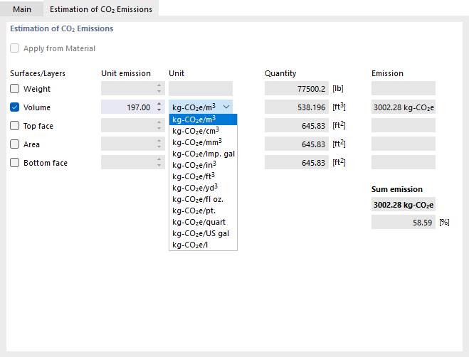
If CO₂ emission estimates are already available for a material of a certain thickness, the "Transfer from Material" check box is enabled by default. This ensures that area-based emission definitions apply and prevents duplicate entries. If you want to define the unit emissions and units for areas with a specific thickness separately, deselect the check box.
Select which thickness parameter is relevant for estimating CO₂ emissions: weight, volume, top surface, surface, or bottom side. In the “Unit Emission” column, enter the value that one unit of the parameter causes in terms of CO₂. The list in the “Unit” column offers various emission units for CO₂ equivalents to select from.
The values displayed in the “Quantity” column for weight, volume, area, and top/bottom side are derived from the properties of the surfaces to which the thickness is assigned. The “Emission” is calculated from these values and the unit emission.
The “Total Emissions” indicate the CO₂ equivalents caused by all surfaces of the thickness. Furthermore, the component of total emissions attributable to this thickness is displayed.
