


A member spring describes the spring stiffness and the effective area of a member in its longitudinal direction. It allows you to represent stiffness specifications for force-distance relations in the model.
Main
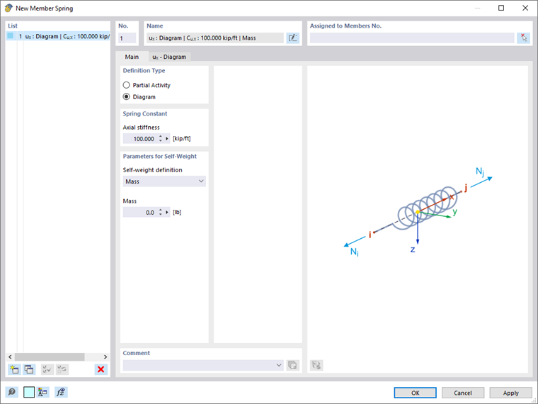
In the Main tab, you can specify the definition type, among other things. It affects the concept of the second tab.
Definition Type
Select the "Partial Activity" option to define a spring that is effective with a constant stiffness over a defined area. You can define the parameters in the ux – Partial Activity tab.
The "Diagram" option allows you to describe the spring stiffnesses individually in a force-distance diagram. You can enter the corresponding specifications in the ux – Diagram tab.
Spring Constant
The spring constant describes the stiffness of the member in its longitudinal direction x according to the general relation:
|
Cu,x |
Spring constant in the member longitudinal direction |
|
E |
Modulus of elasticity |
|
A |
Cross-sectional area |
|
l |
Member length |
Thus, the stiffness is specified directly for a spring member and is not determined from the modulus of elasticity and the member cross-section.
Parameters for Self-Weight
There are three options in the list for defining the self-weight of the spring:
- Mass: Enter the mass of the entire spring member.
- Mass / Length: Enter the length-related mass.
- Specific Weight: Enter the specific weight and the cross-sectional area.
ux – Partial Activity
If you have selected the "Partial Activity" definition type, you can describe the spring properties in detail in this tab. It is also possible to assign nonlinear parameters. Your specifications are dynamically represented in the diagram on the right.
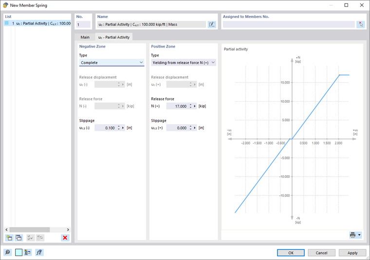
Define the effect of the spring for the "Negative Zone" and for the "Positive Zone". In the "Type" list, various criteria for the effectiveness of the spring are available for selection.
- Complete: The displacement ux is possible to the full extent.
- Fixed from release displacement ux: The spring is only effective up to a certain displacement. If it is exceeded, a fixed connection becomes effective and the spring corresponds to a rigid member ("stop").
- Failure from release force N: The spring is only effective up to a certain force. If it is exceeded, the spring fails.
- Yielding from release force N: The spring is only effective up to a certain force. If it is exceeded, only the displacement ux increases; the force N does not increase anymore.
All spring types can be combined with "slippage" ux,s. It allows you to represent a spring's property that should only act after a certain displacement.
ux – Diagram
In this tab, you can describe the spring properties in detail for the "Diagram" definition type. Again, your specifications are dynamically represented in the diagram on the right.
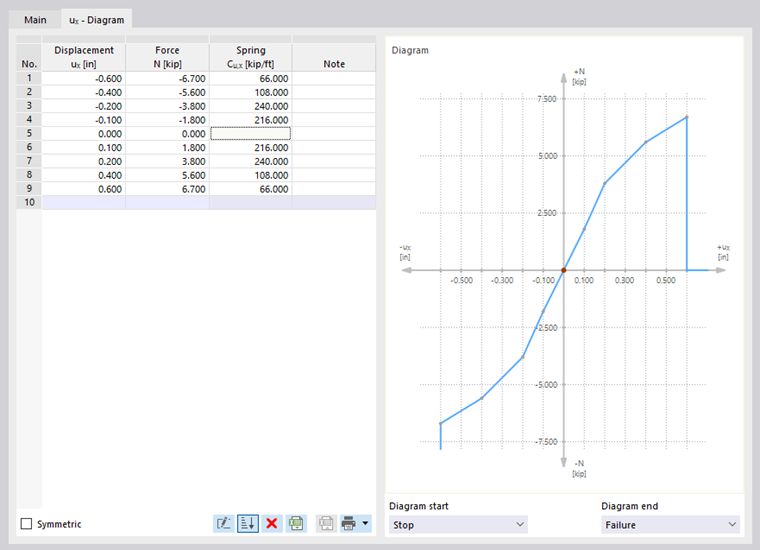
In the "Displacement" column, define the number of definition points for the work diagram by entering the corresponding values. In the "Force" column, you can assign the spring forces to the x-coordinates of the displacements. Based on the entered data, the spring constant Cu,x is determined and entered automatically.
If the order of definition points is incorrect, you can sort the entries in ascending order by using the
![]() button.
button.
The following criteria are available for selection for the "Diagram start" and the "Diagram end":
- Failure: The spring is only effective up to a certain force or displacement. If it is exceeded, the spring fails.
- Yielding: The spring is only effective up to a certain force. If it is exceeded, only the displacement ux increases; the force N does not increase anymore.
- Continuous: Beyond the definition range, the spring constant of the last step is applied.
- Stop: The spring is only effective up to a certain displacement. If it is exceeded, a fixed connection becomes effective and the spring corresponds to a rigid member.