


In the Tools → Modify Lines menu, there are two editing functions that you can use to create center lines between both parallel and non-parallel lines (see the image
Modeling Tools
). Alternatively, you can use the buttons
![]() or
or
![]() available in the CAD toolbar.
available in the CAD toolbar.
Setting Center Line Between Center Points
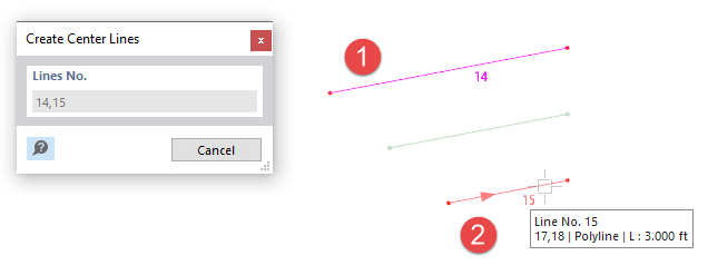
The Set Center Lines function creates a line in the middle between two lines. Select these lines one after the other in the work window by clicking on them. As soon as you move the pointer over the second line, you can see the center line in a preview.
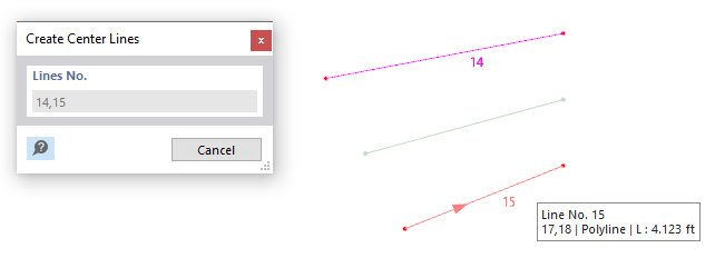
If the lines are parallel, the center line is created between the lines and the length is adjusted. If the lines are not parallel, the center line is determined by the center points between the start and end points of the lines.
Setting Center Line by Angle Axis
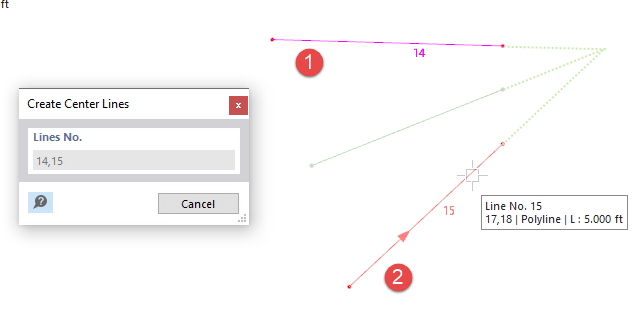
Use the Set Center Lines | Angle Axis function to create a center line between two lines that are not parallel. In contrast to the Center Lines function, the center line refers to the angle bisector that is placed at the intersection of both lines. This is shown in dotted lines in the following image.
If the lines are parallel, the center line is created in the middle between these two lines.