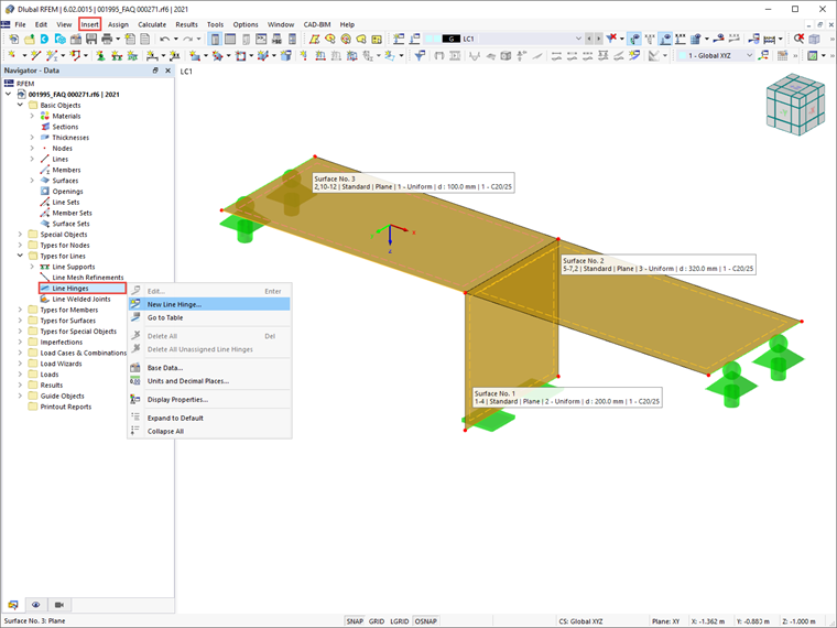
Surfaces that touch each other on one line are rigidly connected at it. A line hinge allows you to control certain degrees of freedom to limit the transmission of internal forces and moments.

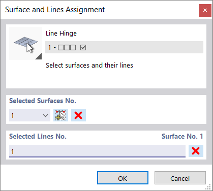
It is necessary to assign the line to both a line and a surface. You can define the line and surface numbers graphically.
Main
The Main tab manages the basic hinge parameters.
Hinge Conditions
The hinge conditions are divided into three "Translational" and one "Rotational" degree of freedom. The former describes the displacements in the direction of the local axes, the latter describes the rotation about the longitudinal line axis.
To define a hinge, tick the check box for the respective axis. The check mark indicates that the line's displacement in or rotation about the corresponding direction is possible. The constant of the translational or rotational spring is then set to zero. You can adjust the "Spring constant" anytime in order to model an elastic hinge.
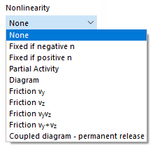
In the "Nonlinearity" column, you can specifically control the transfer of internal forces and moments for each component. Depending on the degree of freedom, suitable entries are available for selection in the list of nonlinearities.
Fixed if Negative or Positive Internal Force
The settings allows you to easily control whether the hinged effect is only given for positive or negative forces or moments. If the internal force acts in the specified direction of the surface axis, the connection is fixed and the force or moment is transferred.
For the effect of the internal force (negative or positive), the line hinge coordinate system has to be related to the "connecting surface"—that is, the surface for which the line hinge is not defined. For example, if only compression forces are transferred, "Fixed if positive vy or vz" would be correct if the hinge axis y or z points in the direction of the desired load transfer.
When you select a different nonlinearity, you can define the parameters in the Partial Activity, Diagram, Friction, Coupled Diagram, or Force/Moment Diagram tabs.
Options
This section provides additional setting options.
Slab-Wall Connection
The control panel allows you to specify specific properties of the line hinge in order to limit the transfer of moments. You can define the parameters in the Slab-Wall Connection tab.
Hinge Rotation φy and φz
If you check the control box, the degrees of freedom φy and φz are set to zero. In most cases, this has no practical significance for construction, as the influence is negligible. However, this option can be useful for special modeling—for example, for a circular cover that rests on a container and is only intended to transfer vertical forces. With a torsional moment in the center of the cover, the degree of freedom φz would prevent free rotation. By releasing the degree of freedom, the cover rotates as desired.
Partial Activity
The Partial Activity of a hinge component is available as a nonlinear property of the member hinge (see the image Selecting Hinge Nonlinearity).

Define the effect of the hinge for both the "Negative Zone" and the "Positive Zone". The "Type" list offers various criteria for the effectiveness of the hinge.
- Complete: Due to the hinge, displacement or rotation is possible to the full extent.
- Fixed from release displacement/rotation: The hinge is only effective up to a certain displacement or rotation. If the limit is exceeded, a fixed connection or restraint becomes effective.
- Failure from release force/moment: The hinge is effective only up to a certain force or moment. If the limit is exceeded, the hinge fails and no longer transfers the internal force or moment.
- Yielding from release force/moment: The hinge is effective only up to a certain force or moment. If it is exceeded, the strains still increase, but not the internal force or moment.
- Spring ineffectiveness: In the case of a hinge with spring stiffness, the hinge component is not effective.
Most hinge types can be combined with a "Slippage", which means that the hinge becomes effective only after a certain displacement or rotation.
Diagram
The Diagram of a hinge component is available as a nonlinear property of the hinge (see the image Selecting Hinge Nonlinearity).
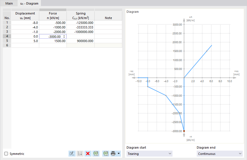
Define the number of definition points for the work diagram by entering the corresponding values in the "Displacement" or "Rotation" column. Then, in the "Force" or "Rotation" column, you can assign the x-coordinates of the displacements or rotations with the hinge forces or moments.
You can import the diagram from an Excel table using the
![]() button. If the order of the definition points is incorrect, you can sort the entries in ascending order using the
button. If the order of the definition points is incorrect, you can sort the entries in ascending order using the
![]() button.
button.
The following criteria are available for selection for the "Diagram start" and the "Diagram end":
- Tearing: The hinge spring is only effective up to the maximum value of the force or moment. If it is exceeded, the full hinge effect is reached. Internal forces and moments are no longer transferred.
- Yielding: The hinge spring is effective up to the maximum value of the force or moment. If it is exceeded, the strains still increase, but not the internal forces or moments.
- Continuous: Beyond the definition range, the spring constant of the last step is applied.
- Stop: The allowable deformation is limited to the maximum value of the displacement or rotation. If it is exceeded, the hinged effect is suspended and a fixed connection or restraint becomes effective.
Friction
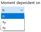
The "Nonlinearity" list offers four options to define the Friction of a translational hinge depending on another hinge component (see the image Selecting Hinge Nonlinearity).
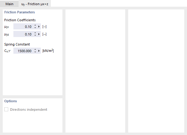
The transferred hinge forces are related to the axial or shear forces acting in another direction. Depending on the selection in the "Main" tab, the friction depends on only one or two support forces. The following correlation exists between the friction force of the hinge and the axial or shear force:
Coupled Diagram
The Coupled diagram – permanent release option allows you to consider the failure criterion for one degree of freedom for the other directions as well: If a certain internal force cannot be transferred, all other degrees of freedom are also released and the surfaces are completely decoupled.

Force/Moment Diagram
For a φx-hinge with nonlinear properties, you can define a Force/Moment Diagram.
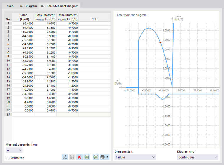
Define the definition points with values for "Force" and the corresponding "Maximum moment" and "Minimum moment". The moments of area mx can be related to the axial forces n or the shear forces vy or vz. Define that reference using the list at the bottom of the dialog section.
The following criteria are available for selection for the "Diagram start" and the "Diagram end":
- Tearing: The hinge stiffness is effective only up to the start or end value of the force. No moments are transferred beyond the definition range.
- Yielding: If the start or end value of the force is exceeded, the forces increase, but not the moments.
- Continuous: Beyond the definition range, the hinge stiffness of the last step is applied.
Slab-Wall Connection
In the case of slab-wall connections in masonry structures, moments are not transferred indefinitely, but only depending on the axial forces. In the Slab-Wall Connection tab, you can limit the maximum and minimum moments by means of a force/moment diagram that RFEM generates on the basis of the geometry parameters.
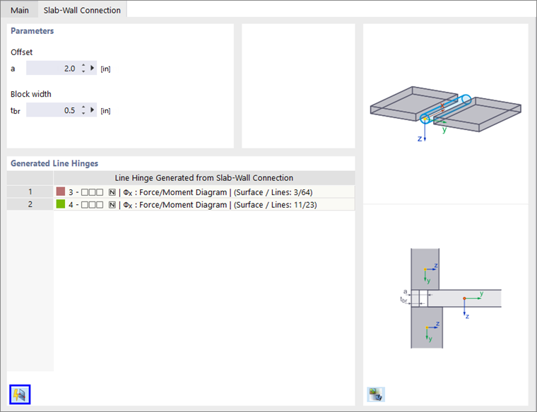
Parameters
Enter the "Offset" and, if available, the "Block width" whose values are required to determine the hinge stiffnesses. The parameters are shown in the dialog graphic.
Generated Line Hinges
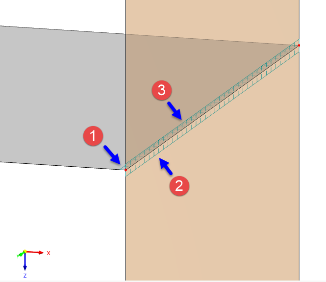
In order to create line hinges, it is necessary to assign a slab surface and a wall connection line (see the image Assigning Line Hinge). Then, click the
![]() button at the end of the section. RFEM creates one line hinge for a story wall, and two line hinges for two stories.
button at the end of the section. RFEM creates one line hinge for a story wall, and two line hinges for two stories.
The generated line hinges are created as new types that cannot be edited. Thus, there are three line hinges available for a slab with a story wall below and above:
- Original line hinge of a slab with definition parameters for wall hinges (1)
- Generated line hinge for a connection to the bottom wall (2)
- Generated line hinge for a connection to the top wall (3)
You can check the parameters of a generated line hinge as follows: Select the type in the list, then activate the Force/Moment Diagram tab (see the image Defining Force/Moment Diagram).