


Corners in surface models may lead to singularity effects. RFEM offers two functions with which you can adjust corners using chamfered edges or fillets. They are available in the Tools menu → Modify Lines. Alternatively, you can use the
![]() or
or
![]() buttons available in the CAD toolbar (see the image
Modeling Tools
).
buttons available in the CAD toolbar (see the image
Modeling Tools
).
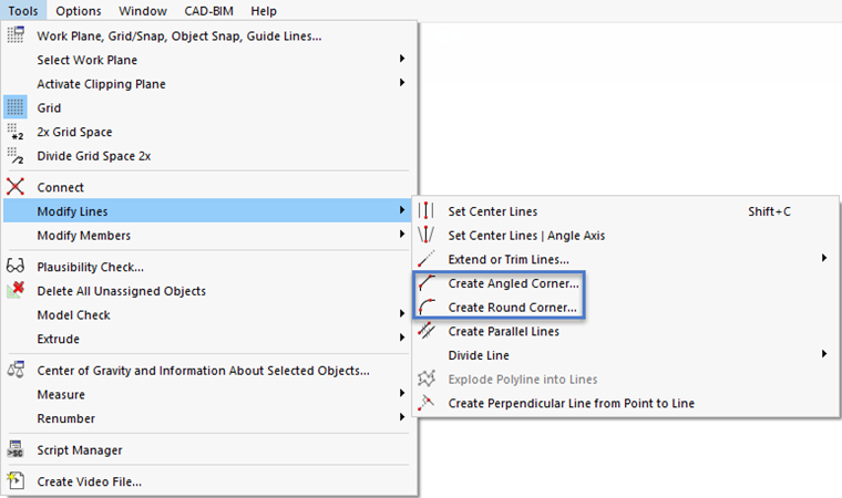
Create Angled Corner
The Create Angled Corner function creates a new line in the corner area, cutting the edge at the corner node.
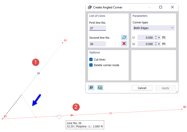
List of Lines
Select the lines one after the other in the work window by clicking the mouse, or enter the line numbers. You can use the
![]() button to change the order of the line numbers. The
button to change the order of the line numbers. The
![]() button deletes the line numbers.
button deletes the line numbers.
Parameters
Two corner types are available in the drop-down list to create the chamfer:
- Both Edges: The first line is shortened by the length L1, the second line by the length L2.
- Edge and Angle: The first line is shortened by the length L1. It is connected to the second line by the angle α. The angle is related to a coordinate system that is oriented clockwise.
Options
If the "Cut lines" check box is selected, the projecting lengths of the original lines are deleted in the corner area after the chamfer has been created.
The "Delete corner node" option also removes the node at the original intersection.
Create Round Corner
The Create Round Corner function creates a new arc at the intersection of two lines and rounds out the corner area.
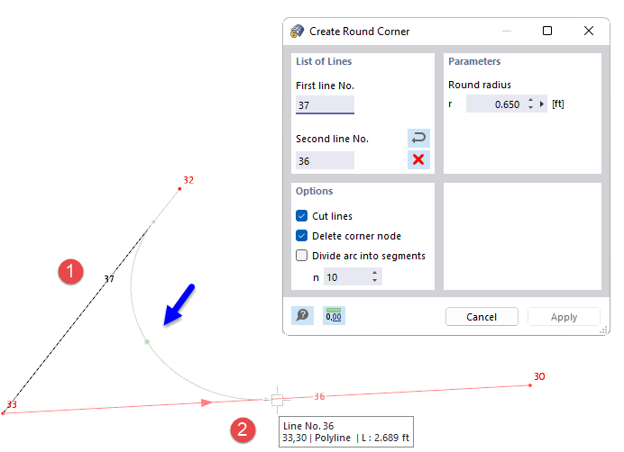
List of Lines
Select the lines one after the other in the work window by clicking, or enter the line numbers. You can use the
![]() button to change the order of the line numbers. The
button to change the order of the line numbers. The
![]() button deletes the line numbers.
button deletes the line numbers.
Parameters
Specify the fillet radius r of the arc to be created between the lines.
Options
If the "Cut lines" check box is selected, the projecting lengths of the original lines are deleted in the corner area after the fillet has been created.
The "Delete corner node" option also removes the node at the original intersection.
With the "Divide arc into segments" check box, you can divide the arc into a corresponding number (n) of straight segments.