


A free line load acts as a uniform or linearly variable force along any freely definable line of a surface. No FE nodes are generated along this line.
In the list, select the "Load Case" to which you want to assign the load.
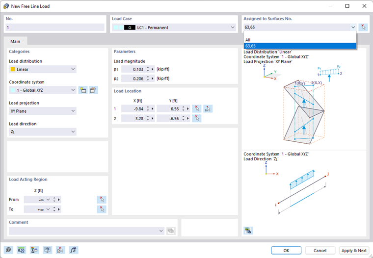
In the "Assigned to Surfaces" dialog section, you can control the effect of the line load. Several options are available for selection in the list (see the image New Free Line Load):
- "Empty": The load does not act on any surfaces.
- All: The load is applied to all surfaces that are cut perpendicular to the projection plane, starting from the load locations.
- "Number": The load acts only on the surfaces of the specified numbers.
Categories
The following options are available for selection in the "Load distribution" list:
- Uniform: The line load acts with a constant magnitude.
- Linear: The load has a linearly variable magnitude.
If the line load does not refer to the global "Coordinate system" XYZ, you can select a user-defined coordinate system or create a new one.
In the "Load projection" list, select on which of the global planes (XY, YZ, or XZ) you want to project the load. From the load location points, RFEM "constructs" two straight lines perpendicular to this projection plane. The start and end points of the line load result from the intersection points of this straight line with the surfaces. This way, you can quickly apply the same loads to several surfaces.
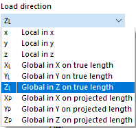
Select the "Load direction" from the list to define the effect of the load. Depending on the coordinate system, the local surface axes x, y, z, the global axes X, Y, Z, or the user-defined axes U, V, W are available for selection.
Parameters
Specify the "Load magnitude" of the force. For a linearly variable load, you have to enter two load values.
Load Location
Enter the coordinates of both load positions. You can also use the
![]() button to define the points graphically. The reference points of the load may also lie outside the surfaces.
button to define the points graphically. The reference points of the load may also lie outside the surfaces.
Load Acting Region
As described above, the load acts on the surfaces that are cut perpendicular to the projection plane, starting from the load location. If you have selected the "All" option in the Assigned to Surfaces dialog section, you can limit the effect of the load by means of geometric criteria.
By default, the load acts indefinitely in the interval from -∞ to +∞. You can use the "From" and "To" text boxes to reduce the load effect to certain zones.