User-defined coordinate systems allow for easier input of model parts that do not lie in any of the global axis planes. They have nothing to do with the axis systems of lines, members, or surfaces.
The default is the "Global XYZ" coordinate system related to the global XYZ axes and the origin.
You can also open the "Coordinate System" dialog box using the
![]() button next to the list of coordinate systems (see the image Selecting Coordinate System).
button next to the list of coordinate systems (see the image Selecting Coordinate System).
Coordinate System Type
The list provides several options for defining a coordinate system:
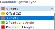
- Offset XYZ: The origin of the global XYZ coordinate system is moved to another point.
- 3 points: The coordinate system is defined by three points.
- 2 points and angle: The coordinate system is defined by two points via a plane and a rotation angle.
- Point and 3 angles: The coordinate system is defined by a point and three rotation angles of the global axes.
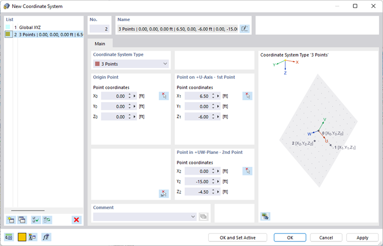
Origin Point
Enter the zero point of the new coordinate system or define it graphically with the
![]() button.
button.
Points / Rotation
In the other dialog sections, you can define the points or rotation angles, depending on the coordinate system type. Please note that the three points must not lie on a straight line.
The axes of a user-defined coordinate system are referred to as U, V, and W (see the graphic in the New Coordinate System dialog box).
Example
To define a coordinate system for the roof plane, place the "Origin Point" in a frame corner. Select the ridge node of the corresponding frame beam as the "Point on +U-Axis" and another frame corner on the same hall side as the "Point in +UW-Plane".
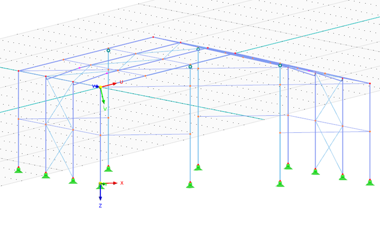
The grid refers to the UV, VW, and UW work planes where you can define new objects.
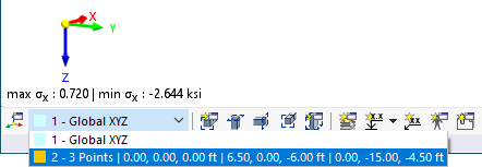
In the list available in the bottom left of the CAD toolbar, you can switch between the coordinate systems.