


1D Elements
For member elements, it is assumed that the cross-section remains planar during deformation. "1D elements" are used to represent beams, trusses, ribs, cables, and rigid couplings. A 1D member element has a total of twelve degrees of freedom − six at the start and six at the end of the element, for both the displacements (ux, uy, uz) and rotations (φx, φy, φz). When calculating structural data linearly, tension, compression, and torsion are expressed as linear functions of the member axis x, independent of bending and shear. They are approximated by a third-order polynomial in x, including the influence of shear stresses from the shear forces Vy and Vz. The stiffness matrix KL(12, 12) describes the linear behavior of the 1D elements. The mutual interaction between axial force and bending for geometrically nonlinear problems is expressed in the stiffness matrix KNL(12, 12). For more information, see [1] and [2].
For calculations according to the large deformation analysis, we recommend using a line mesh refinement so that member results can be determined with corresponding accuracy.
2D Elements
For surfaces, 2D elements are created. Wherever quadrangular elements cannot be used, the mesh generator inserts triangular elements.
The degrees of freedom of quadrangular and triangular elements in corner nodes are the same as for 1D elements: degrees of freedom of displacement (ux, uy, uz) and rotation (φx, φy, φz). This ensures compatibility between 1D and 2D elements in the nodes. The parameters are defined in the planar local coordinate system of elements and are converted into the global coordinate system when composing the global stiffness matrix.
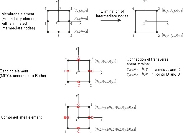
The image Quadrangular Elements for Shells shows the approach for planar shell elements. It is based on the Mindlin/Reissner theory. To ensure direct coupling with member elements, a quadratic approach is chosen in the shell plane (ux, uy). Eliminating the intermediate nodes creates a four-node element with additional rotational degrees of freedom in the x, y, and z directions. This allows direct coupling with beam elements for plate elements. Based on a mixed interpolation of the transverse displacements, cross-section rotations, and transverse shear strains, the MITC elements (Mixed Interpolation of Tensorial Components) as presented by Bathe and Dvorkin [3] are used: MITC3+ for triangles, MITC4 for quadrangles.
Presently, member elements are considered by directly solving the differential equation according to the second-order analysis. Warping effects cannot be considered when using the Saint Venant torsion.
Membrane calculations are based on the principles of Bergan [4] [5] [6]. For triangular elements, for example, the basic functions are divided into three rigid-body deformations, three constant conditions of strain, and three special linear gradients of stress and strain. The deformation field in an element is quadratic and the stress field is linear. The element stiffness matrix KL is subsequently transformed into nine collective parameters of the types ux, uy, φz. The components of this matrix are inserted together with the components for bending and shear into the overall stiffness matrix (18, 18). This matrix is the result of the Lynn/Dhillon concept. This way, Mindlin plates (plates with distinct shear deformation) are applied and analyzed according to Timoshenko. In this way, RFEM finds the correct solution for both thick and thin plates (Navier plates).
In the case of geometrically nonlinear problems, the above-mentioned split of the stress-strain condition into a planar state and in bending/shear is not possible. The mutual influences of these states are considered in the matrix KNL. RFEM uses a rather simple but effective form of the matrix KNL that is based on the approaches of Zienkiewicz [7]. The square component ε2 of the Green/Lagrange strain tensor ε = ε1 + ε2 is applied. A linear distribution of uz(x, y) of the planar stress condition and linear distributions of ux(x, y) and uy(x, y) of the interaction with bending is assumed. This assumption is possible because the main interaction effect depends on the first derivative of the differential equation, and the influence of higher-order components decreases very rapidly with the division into smaller elements. The correctness of this procedure has been proven in several numerical analyses.
3D Elements
3D elements are used for solids. The following element types are implemented in RFEM: tetrahedron, pentahedron (prism, pyramid), and hexahedron. For detailed information about applied elements and matrices, see Sevcik's 3D Finite Elements with Rotational Degrees of Freedom [8] for details. You can request the documentation from Dlubal Software.

In general, all rotational degrees of freedom must be regarded critically for solids. As the deformation of a solid is solely determined from the displacement vectors, the rotation of a mesh node (for example, due to singularly introduced torsion) does not affect the deformation in the solid.