


Select the model, load, or guide objects you want to rotate. Then, click the
![]() button (see the image
Modeling Tools
). In the "Rotate" dialog box, specify whether the objects are to be copied when rotating, and define the parameters.
button (see the image
Modeling Tools
). In the "Rotate" dialog box, specify whether the objects are to be copied when rotating, and define the parameters.
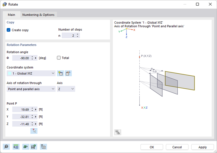
Main
The Main tab manages the basic parameters for rotating objects.
Copy
If the "Create copy" check box is not ticked, the selected objects will be rotated. If you want to create one or more copies, tick the check box. Then, enter the "Number of steps" that describes the quantity of copies.
Rotation Parameters
Enter the "Rotation angle" Φ. The angle is related to a coordinate system that is oriented clockwise. When creating several copies, the "Total" check box controls whether the angle is applied between the individual copies or between the original and the last copy.
Define the "Coordinate system" in which the objects are to be rotated. You can select a user-defined coordinate system from the list or create a new one using the
![]() button.
button.
In the "Axis of rotation through" list, there are two options for defining the axis of rotation:
- Point and parallel axis: The rotation axis runs parallel to an axis of the specified coordinate system. Select the "Axis" in the list to the right, and enter "Point P" that lies on the rotation axis.
- 2 points: The axis lies anywhere in space. Enter the coordinates for "Point P1" and "Point P2" to define the rotation axis. Use the
 button to define the points graphically.
Numbering & Options
The Numbering and Options tab is only displayed when copying. Here, you can influence the numbering of new objects and make useful settings for copying.
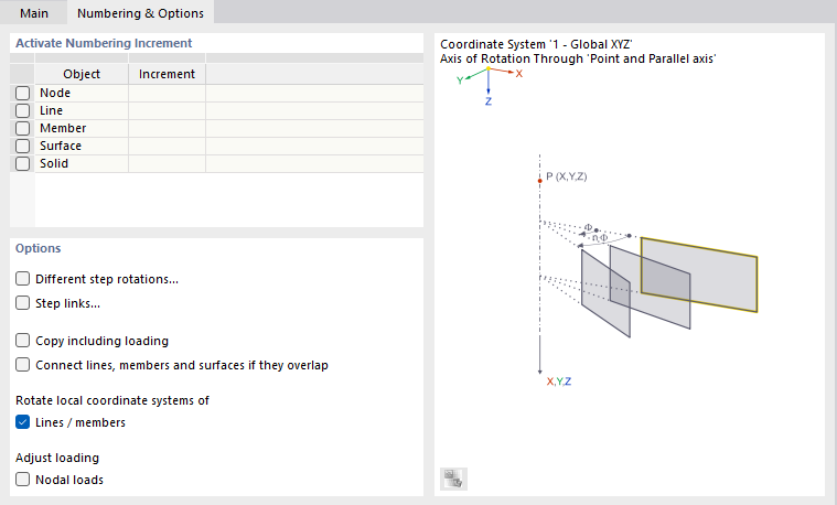
The functions of the tab are described in the chapter Move and Copy . In addition, two check boxes are available that specifically affect the rotation.
The "Rotate local coordinate systems of Lines/members" check box is primarily relevant when rotating vertical lines and members. The setting controls whether the axes are also rotated or realigned, taking into account general specifications (see the chapter Section ).
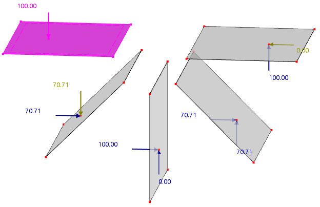
If the "Adjust loading" of the "Nodal loads" check box is selected, the direction of nodal loads defined in the global coordinate system is changed when copying. RFEM converts the loads to the new position in the same manner as local concentrated loads. If the check box is not activated, the global load direction is kept.
Step Rotations
The Step Rotations tab is displayed if at least two copies are specified and the "Different step rotations" check box in the Numbering and Options tab is selected.
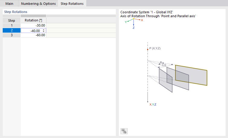
In the table, you can individually define the angles of the "Rotation" between the copies.
Step Links
The Step Links tab is displayed if the "Step links" check box in the Numbering & Options tab is selected. The functions are described in the chapter Move and Copy .