This load generator facilitates the task of applying snow loads to members and surfaces of the model in accordance with standards.

Base
The Base tab manages the roof geometry parameters.
Roof type
The list offers two roof basic shapes to choose from:
- Flat/mono-pitched roof
- Gable roof
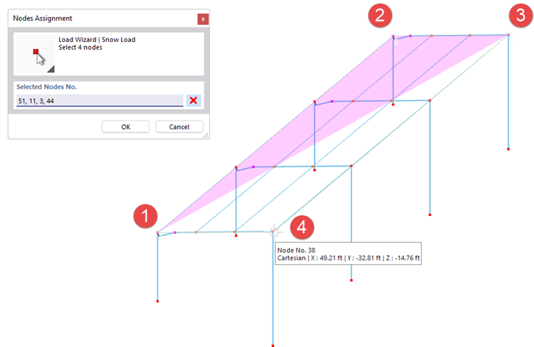
Define the boundary of the roof plane by clicking the four or six corner nodes of the plane(s) one after another in the work window. Use the
![]() button for this.
button for this.
Define loaded roof
The table provides an overview of the properties of the roof plane(s). For a gable roof, the two roof halves are specified. If required, you can use the check boxes to exclude a roof side from the load assignment.
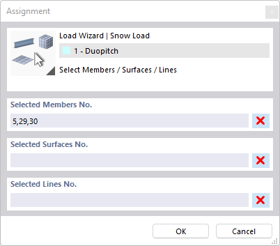
Generated on Members/Surfaces/Lines No.
This section specifies the members, surfaces, and lines that receive a proportional snow load. The entries in the 'Loaded' column are available as soon as the snow load is generated from the complete information using the
![]() button.
button.
To exclude certain members, surfaces, or lines from load transfer, click a field in the 'Without load' column. You can then use the
![]() button to select the objects in the work window that are without load, such as bracings or purlins. You can also specify a pattern member or pattern line that runs parallel to the unloaded members or lines. This saves you from having to select the objects individually.
button to select the objects in the work window that are without load, such as bracings or purlins. You can also specify a pattern member or pattern line that runs parallel to the unloaded members or lines. This saves you from having to select the objects individually.
Options
The 'Partial Areas' check box allows you to generate loads for specific zones of the building envelope. The snow load is applied only to the elements of the areas that you define in the Partial Areas tab.
If you check the 'Ignore New Load-Bearing Objects' box, the snow load acts only on the objects specified in the Generated on Members/Surfaces/Lines No. section. Members, surfaces, or lines that you add later in the load plane do not receive any portions of the snow load.
Partial Areas
In the Partial Areas tab, you can define zones of the roof surface on which the snow load acts. The loads are generated only for the elements of these partial areas. The remaining areas do not receive any snow loads.
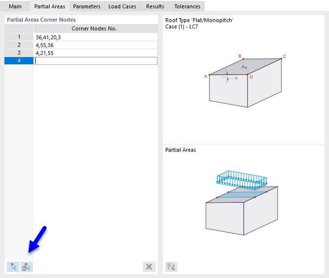
Define the partial areas line by line by entering their 'corner nodes'. With the two buttons at the end of the table, you can also define the partial areas graphically.
|
|
Click the corner nodes of an area in succession (see image Define nodes). |
|
|
Click the cells one after another (see image Select cells). |
Parameters
In the Parameters tab, you can define the load parameters and take special boundary conditions for generation into account.

Definition
If you have taken the location from the online map in the base data in the Model Parameters tab, the definition type 'Map and Parameters' is preset. The snow load is determined automatically. You can also open the snow load map in this tab using the
![]() button.
button.
With the definition type 'User-Defined', you can manually set the snow load zone, altitude, and the value of the characteristic snow load.
Parameters
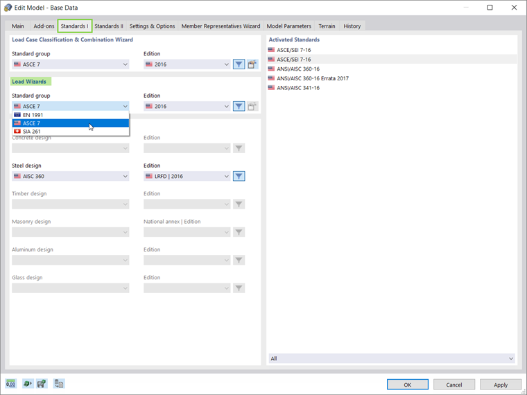
If the 'Load zone' is not entered automatically, you can select it from the list. The entries are aligned with the standard that you defined in the Standards I tab under the model base data.
The 'Altitude' is usually preset from the model parameters, but it can also be defined manually. It affects the characteristic value of the snow load.
Snow load
The characteristic value of the snow load sk on the ground at the structure is preset from the geographical data. If you want to change the value, check the 'Manual snow load definition' box.
Coefficients
The 'Exposure coefficient' Ce indicates the reduction or increase of the snow load on the roof of the building. In EN 1991-1-3, Table 5.1, you will find recommendations for different terrain conditions.
With the thermal coefficient Ct, you can account for reduced snow loads on roofs with higher heat transfer.
Load distribution
Currently, only trapezoidal loads are generated on members, resulting from the load portions.
Options
Using the check boxes in this section, you can control whether additional snow loads such as 'snow overhang' at the eaves or loads on a 'snow guard' are to be considered (Eurocode only).
If you check the 'Lock for new objects' box, the snow load acts only on the currently existing members, surfaces, or lines of the roof plane(s) according to the definition in the 'Base' tab. Objects that you add later in a roof plane do not receive any portions of the snow load.
The 'Consider member eccentricity' option controls whether the snow load acts on the members in the plane without considering eccentricities (default). If you activate the check box, the load is not applied to members that have an offset from the plane.
The 'Consider cross-section distribution' check box allows you to control whether the snow load also acts on the inclined members resulting from a haunch definition (default). If you activate the check box, the snow load is not applied to members in the load plane that have an irregular cross-section variation (see chapter Cross-section ).
Load Cases
The Load Cases tab controls in which load cases the snow loads are stored.
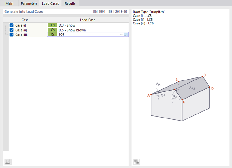
Enter the load case number(s) in the list for generating the snow loads. The alternative load cases are created when additional snow loads or shape coefficients for snow loads on gable roofs apply (see EN 1991-1-3, Figure 5.3). You can create the corresponding load cases using the
![]() button.
button.
Results
In the Results tab, you will find an overview of the parameters for generating the snow loads.
.png?mw=760&hash=d48e0231f870dbde5006d8b4d8c6e14d32797864)
The table specifies the 'shape coefficient' μ and the 'snow load' s. For a gable roof, you can check the values for each load case and each roof side.
Tolerances
In the Tolerances tab, you can influence the criteria according to which members and nodes are assessed as belonging to a plane or line. The parameters are described in chapter Member Loads from Surface Loads .