Surface loads are forces, moments, masses, temperature effects, or imposed deformations that act on surfaces. Openings are excluded from the surface load.
Select the 'Load case' from the list to which the load is to be assigned.
Categories
The following options are available in the 'Load type' list:

| Load type | Description |
|---|---|
| Force | Uniform, linearly variable, or radially acting force on the surface |
| Temperature | Uniform, linearly variable over the surface thickness, or radially arranged temperature load (positive load value: surface or surface top side is heated) |
| Axial strain | Length change ε as elongation or shortening of the surface due to constraint (positive load value: surface is elongated) |
| Precamber | Imposed curvature of the surface |
| Rotary motion | Centrifugal force from mass and angular velocity ω on the surface |
| Mass | Mass uniformly distributed over the surface, relevant for Dynamic Analysis |
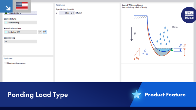
| Ponding | Rain load on multi-curved surfaces (water bags) considering draining portions |
| Form-finding (only for add-on Form-Finding) | Uniform force, stress, or sag for form-finding load (see chapter Form-Finding Loads of the Form-Finding manual) |
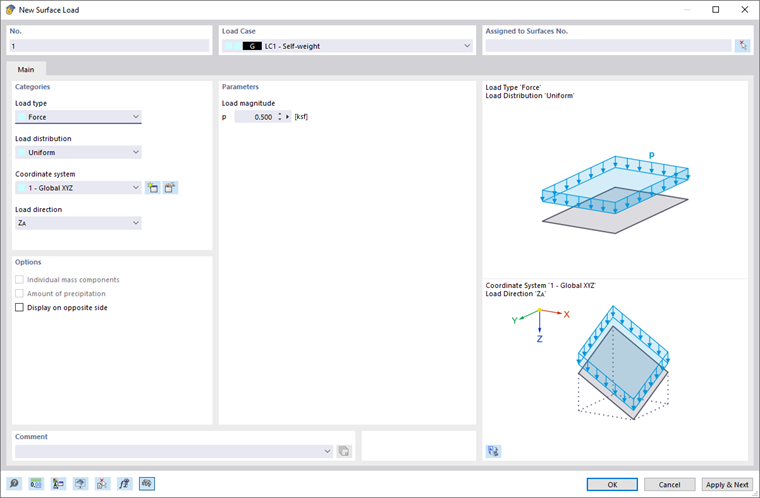
The load type and the effect of the signs are illustrated in the upper dialog graphic.
Various options are available in the 'Load distribution' list to map the arrangement of the load.
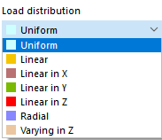
The load distribution scheme is illustrated in the upper dialog graphic. In the 'Parameter' section, you can then specify the values, reference nodes, and other parameters of the load.
In the 'Coordinate system' list, specify whether the load acts in the direction of the local xyz-surface axes or the global XYZ axes. Alternatively, you can select or create a user-defined coordinate system. The local axis z is oriented perpendicular to the surface.
Select the 'Load direction' from the list to define the effect of the load. Depending on the coordinate system, the local surface axes x, y, z, the global axes X, Y, Z, or the user-defined axes U, V, W are available for selection.
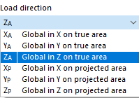
The surface load can be related to the true surface (like a self-weight) or the projected surface (like a snow load). The load direction is illustrated in the dialog sketch.
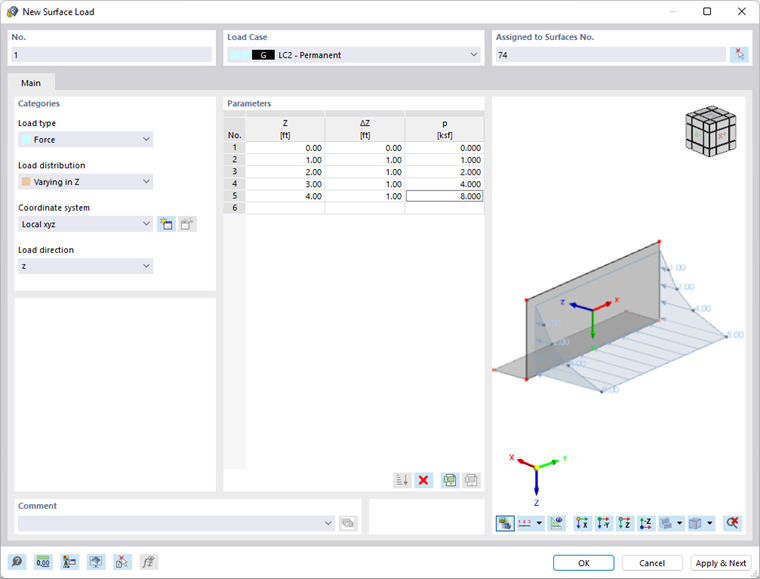
Parameter
Enter the load value for the force, moment, or mass. For point or variable loads, multiple input fields are available where you can describe the line load. The meaning of the parameters is illustrated in the load sketch.
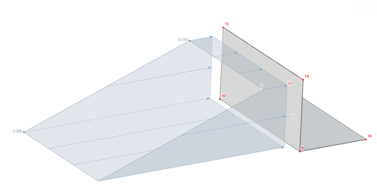
For the 'Variable in Z' load type, a table is available to describe the Z ordinates with the associated load values.
Options
With the 'Display on opposite side' option, you can influence the representation of the load vectors.