Guidelines represent a grid of axes and rows underneath the graphical workspace. The intersection points of guidelines are also snap points for the graphical input – provided that the object snap for guidelines is activated (see the chapter Object Snaps). You can also do it by quick control using the
![]() button in the
CAD Toolbar
.
button in the
CAD Toolbar
.
Guidelines may be parallel to the axes of the global coordinate system XYZ. However, free angles and polar alignments are also possible. Spacings between guidelines may also be arbitrary.
To display or hide the guidelines, use the
![]() button in the CAD toolbar.
button in the CAD toolbar.
List
In the list, the guidelines are sorted by work planes and types. As usual, you can create new guidelines or copy selected entries by using the
![]() and
and
![]() buttons available at the end of the list.
buttons available at the end of the list.
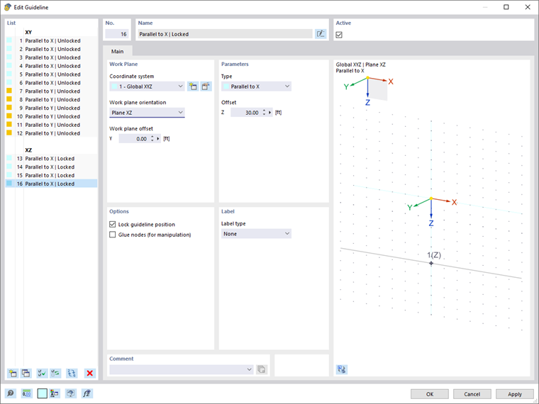
Name
The guideline description is created automatically but can be adjusted by the
![]() button.
button.
Active
Use the check box to control whether the guideline is displayed in the work window.
Work Plane
Define the "Coordinate system" which the guideline is related to. You can select a user-defined coordinate system from the list or create a new one using the
![]() button.
button.
The "Work plane orientation" determines the plane in which the guideline is created. For the global coordinate system, you can select the planes XY, YZ, and XZ. For a user-defined coordinate system, you can select the planes UV, VW, and UW.
With the "Work plane offset", you can arrange the guideline at a certain distance parallel to the work plane. A positive value moves the guideline in the direction of the axis, a negative value in the opposite direction.
Parameters
The "Type" controls how the guideline is created. Several options are available in the list.
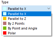
| Type | Explanation |
|---|---|
| Parallel to X / Y / Z | The guideline is created parallel to one of the global axes. Specify the offset that describes the distance from the respective global axis. |
| Parallel to U / V / W | The guideline is created parallel to one of the axes of the user-defined coordinate system. |
| By 2 Points | The guideline is defined by two points in the work plane. Enter the coordinates of both points or determine them graphically with the
|
| By Point and Angle | The guideline is defined by a point and a rotation angle in the work plane. Enter the coordinates of the point and the rotation angle α (see the dialog graphic). |
| Polar | The guideline is created in a circle around a point by the radius r. Enter the coordinates of the center or determine the point graphically using the
|
Options
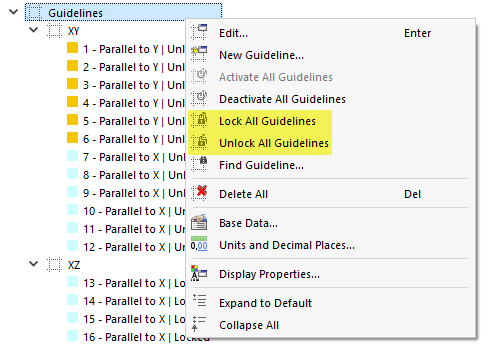
By activating the "Lock guideline position" check box, you can control whether a guideline can be selected, edited, or moved. A locked guideline is fixed in the work window. Thus, it cannot be moved or deleted unintentionally, and it does not represent an obstacle when entering model objects.
You can lock and unlock guidelines in the list, either individually or in groups (multiple selection). The general shortcut menu (right-click in an empty space of the work window) as well as the shortcut menu in the navigator also provide the option to lock or unlock all guidelines at once.
If the "Glue nodes (for manipulation)" check box is selected, every node you have defined on the guideline is also moved when moving the guideline.
Label
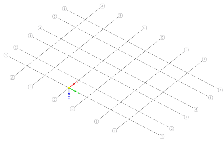
The default setting is that no descriptions are displayed for guidelines. In the "Label type" list, however, you can select whether to use numbers, letters, or names, as shown in the image Guidelines Parallel to Axes X and Y.
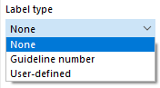
Use the "User-defined" option to assign individual descriptions to the guidelines.
Setting Guidelines Graphically
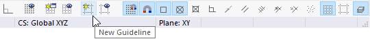
Use the
![]() button in the CAD toolbar to set the guidelines directly in the work window.
button in the CAD toolbar to set the guidelines directly in the work window.
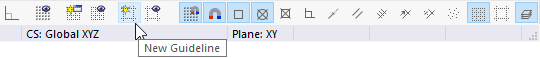
The "New Guideline" dialog box appears.
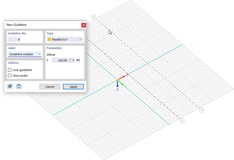
The guideline—like any other object—is placed in the current work plane. First, define the Type and other options in the small "New Guideline" dialog box. When you move the mouse in the work plane to specify the "Offset", the guideline is shown in a preview. By clicking a point, you set the new guideline; then you can continue with the next guideline.
Editing Guidelines
Guidelines are objects for which you can use the graphical editing functions. To move or copy a guideline, select it using one of the selection options first.
If you cannot select a guideline in the work window, it is locked. In this case, right-click in an empty space of the work window, then select the Unlock All Guidelines item available in the shortcut menu (see also the image Guideline Shortcut Menu in Navigator).